Connections
Technical Guide 1-3
Connections
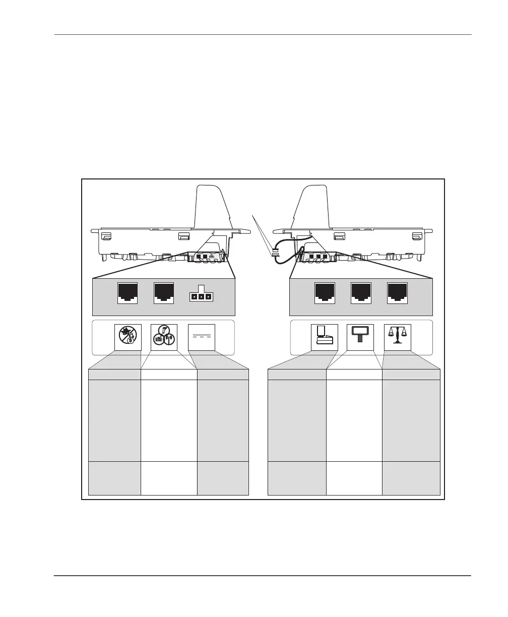
Two connector panels are located on either side of the scanner as shown in
Figure 1-2. The appearance of these panels will vary depending upon the
factory options purchased with your model. Additionally, a service “pig-
tail” extends from the scanner’s base to connect the control panel cable
from the Bonnet area.
Figure 1-2. Connectors
POS TERMINAL REMOTE DISPLAYAUXILIARY PORT SCALE HOSTEAS PORT
Connection to
this port is
Optional
Scale Data (dual
cable scanner/scale)
Drives Remote Display· Label Data
· Scale Data (for
single cable interfaces)
· Application Download
(where appropriate)
· Test Port
· On Screen
Programming (OSP)
· Application Download
· RS-232 Handheld
Scanner Input
· Auxiliary RS-232
Label Data Output
Models with scale
only
Connection to
external EAS device.
Controls EAS
deactivation system.
Dual cable units only.
(Scale connection may
be handled through
POS Terminal port)
POS Terminal Remote DisplayAux. PortEAS Port Scale Host
0.00
POWER
AC Brick Input
OR
Power off Terminal
(POT) Brick Input
Power
Control Panel
Service Loop
Scanner Right Profile Scanner Left Profile
 Loading...


