Do you have a question about the Datex-Ohmeda Aespire S/5 and is the answer not in the manual?
Perform visual and basic checks of the equipment before operation.
Verify gas supply connections, pressures, and safety.
Test gas flow controls, pressure relief mechanisms, and alarms.
Check for pressure issues related to vaporizer installation.
Verify system integrity at low pressure to detect leaks.
Confirm the proper functioning of all system alarms.
Check breathing circuit components for leaks and proper function.
Test the performance and accuracy of the auxiliary oxygen flowmeter.
Verify the performance and calibration of the integrated suction regulator.
Assess system behavior and alarms during a power interruption.
Ensure the system meets electrical safety standards and regulations.
Covers maintenance and service procedures for the associated ventilator unit.
Procedure to safely release residual gas pressure before maintenance.
Steps for accessing internal components through the rear panels.
Instructions for disassembling and removing the machine's tabletop.
Steps for replacing the filter located in the pipeline gas inlet.
Procedure for changing the machine's primary drive gas supply.
Maintenance procedures for the gas cylinder supply modules.
Steps for replacing the main system power switch assembly.
Procedures for servicing and replacing flowmeter module components.
Maintenance and replacement of components within the vaporizer manifold.
Steps for replacing the Auxiliary Common Gas Outlet selector switch.
Maintenance procedures for the ACGO port flapper valve.
Procedures for rerouting the sample gas return line connection.
Steps for replacing the Adjustable Pressure Limiting (APL) valve.
Procedures for replacing the bag support arm assembly.
Steps for replacing the auxiliary oxygen flowmeter unit.
Procedures for replacing the suction control module assembly.
Replacing individual components within the ABS breathing system.
Procedure for replacing the machine's mobility casters.
Replacing the task light illumination and its associated switch.
Procedures for replacing the display arm or its connecting cables.
Specific steps for ProTIVA model display and cable replacement.
Outlines the scope and content covered in this technical reference manual.
Refers to necessary user reference manuals for performing service.
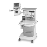
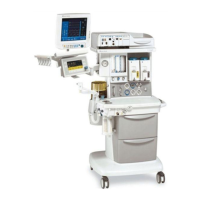
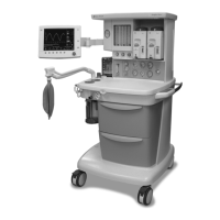
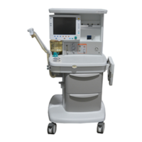
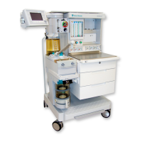
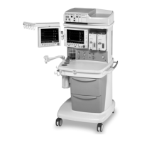
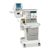
Provides a general description of the S/5 Aespire anesthesia system.
Details standard and optional configurations available for the machine.
Identifies key components and their general locations on the machine.
Explains the meaning of various symbols used in the manual and on the device.
Provides a high-level overview of the section's topics.
Explains how gases move within the anesthesia delivery system.
Details gas pathways within the patient breathing circuit.
Schedule and procedures for performing planned maintenance tasks.
Tests for the proper functioning and accuracy of the auxiliary O2 flowmeter.
Tests for the performance and calibration of the integrated suction regulator.
Procedures for testing and adjusting primary gas supply regulators.
Procedures for testing and adjusting secondary and balance regulators.
Calibrating the needle valves for accurate gas flow adjustment.
Calibrating the gas proportioning link system for correct gas ratios.
Procedures for testing and adjusting the O2 flush regulator.
Procedures for zeroing and checking the accuracy of the airway pressure gauge.
General guidance for diagnosing and resolving common system issues.
Procedures and guidance for identifying and isolating leaks in the breathing system.
Lists specialized tools required for servicing the anesthesia machine.
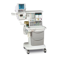
Identifies external components visible from the front of the machine.
References for external components shown in front view diagrams.
Identifies external components visible from the rear of the machine.
Details the mounting of the control module for ProTIVA models.
Lists components specific to the Aespire 100 model.
Details components located on the front panel, including gauges and switches.
Lists components found on the rear panel of the machine.
Identifies components located on the machine's tabletop.
Details components located on the right side of the machine.
Identifies external components in the lower assembly.
Details the components within the Vent Engine housing.
Lists parts related to display, serial board, AGSS, and sample return.
Lists different types of AC power cords for various regions.
Details components related to the AC power inlet and electrical outlets.
Lists various pipeline inlet fitting types and their associated parts.
Details components for cylinder gas supply connections.
Lists components of the vaporizer manifold assembly.
Details components of the flowmeter module, including regulators and flowtubes.
Lists components for the interface between the ABS and the machine.
Details components for the flush functions and ACGO selector switch.
Lists parts for the Adjustable Pressure Limiting (APL) valve assembly.
Details components of the Bag/Vent switch assembly.
Lists parts for the reusable absorber canister.
Details components of the flow sensor module.
Lists components of the breathing circuit module.
Details parts for the exhalation valve assembly.
Lists components of the bellows assembly.
Details components of the bellows base assembly.
Lists parts for the bag arm assembly.
Lists common and specific parts for the passive AGSS.
Lists common and specific parts for the adjustable AGSS.
Lists common and specific parts for active AGSS configurations.
Identifies key components for continuous and Venturi suction systems.
Lists parts for the suction control module.
Details the components of the Venturi assembly for suction.
Illustrates the overall system connections and modules.
Diagrams of the different gas scavenging system configurations.
Shows the layout and connections of the machine's electrical wiring.
Illustrates the gas pathways and pneumatic components of the system.
Diagrams showing the routing of electrical wiring harnesses.
Wiring harness diagrams specific to the Aespire 100 model.
Diagrams illustrating the machine's internal tubing layout.
Electrical schematic for 100-120V AC inlet with non-isolated outlets.
Electrical schematic for 100-120V AC inlet with isolated outlets.
Electrical schematic for 220-240V AC inlet with non-isolated outlets.
Electrical schematic for 220-240V AC inlet with isolated outlets.
Electrical schematic detailing AC power connections for the Aespire 100.
| Model | Aespire S/5 |
|---|---|
| Manufacturer | Datex-Ohmeda |
| Vaporizer Capacity | Up to 2 vaporizers |
| Power Supply | 100-240 VAC, 50/60 Hz |
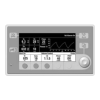
| Ventilation Modes | Volume Control, Pressure Control, SIMV, Manual |
| Tidal Volume Range | 20-1500 ml |
| Inspiratory Time | 0.2 - 5 seconds |
| Oxygen Concentration | 21% to 100% |
| Gas Inlets | O2, N2O, Air |
| Type | Anesthesia Workstation |
| Respiratory Rate | 4-100 breaths per minute |
| PEEP | 0 to 20 cmH2O |