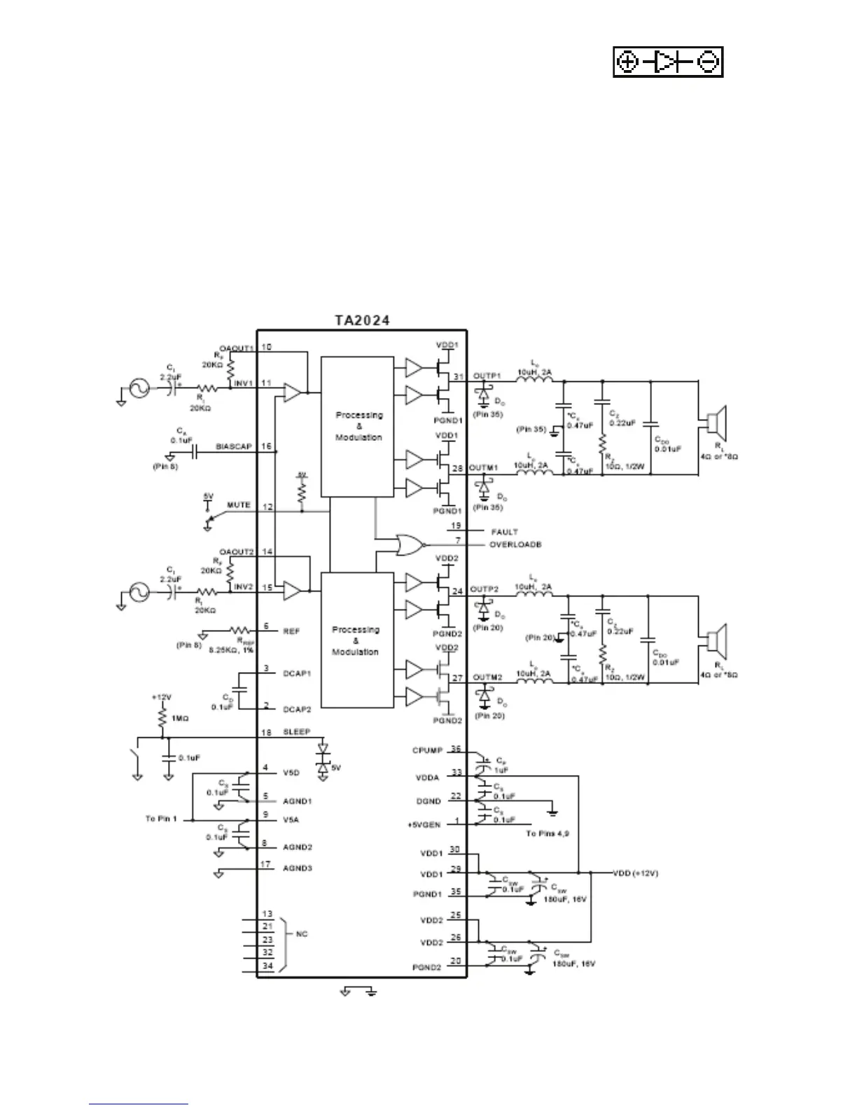
The schematic diagram above is provided for reference. It illustrates the TA-2024 IC and the input
and output circuits on the PCB. CDO are two output capacitors. These capacitors are ideally
placed close to the speaker terminals or crossover input terminals as appropriate.
• Solder the LED to the PCB at point “D” or use the LED wires to place the
LED where desired
• The anode (+) lead is long, the cathode (-) is short
• Mount the LED from the bottom of the PCB
• Insert the anode through the left eyelet and the cathode through the right eyelet
• Wrap each speaker wire through a ferrite core; one wrap per core is all that is required
• Solder the speaker wires to the speaker terminals
• Solder an output capacitor across the speaker terminals in parallel with the speaker wires
• Connect power via the power leads or DC power jack; we recommend a 12VDC, 2000mA power
supply similar to Parts Express model 120-052
• Mount the volume control in the desired location and connect to the amplifier PCB using the 12"
ribbon cable
• Mount the PCB using adhesive pads or with a zip tie
Schematic Diagram: