3KP64 - 2.7
3000PLUS WITH 5D64 INSTRUCTION MANUAL V. SB.2
Daytronic Corporation
2211 Arbor Blvd. Dayton, OH 45439 • (800) 668-4745
Tel: (937) 293-2566 • Fax: (937) 293-2586 • www.daytronic.com
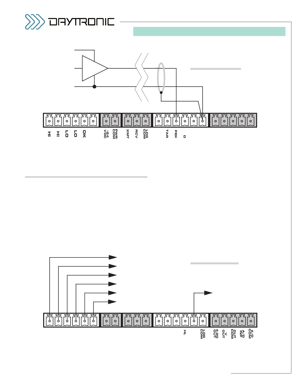
for the other two inputs. You may also use active TTL
logic, as illustrated in Fig. 10.b, to produce the desired
logic condition.
RELAY AND TTL-LEVEL LOGIC OUTPUTS
The six LIMIT RELAY outputs shown in Fig. 10.c are con-
tinuously controlled by the existing limit-zone status of
the “auxiliary” DAC output (Channel 2), if limit monitor-
ing is currently enabled for the meter (see Section 5.E).
There are two independent relays for each limit condi-
tion (“HI,” “OK”, and “LO”), which may be used to switch
power for control action in all types of open-loop or ON-
OFF closed-loop operations—for example, to actuate
alarms or sorting devices, or to start up or shut down
external processes.
As explained in Section 5.E, the contact polarity of the
limit relays may be set to either NORMALLY OPEN or
NORMALLY CLOSED (1) during meter configuration
(Sections 3.B and 4); (2) during run-time via the Configu-
rator’s “Live Output Window” (Section 4.D); or (3) by
direct application of the
POLARITY (POL) command
(Appendix A). A normally
open relay will close on
occurrence of the triggering limit condition (and vice
versa).
The TTL-level “HAVE PEAK” output is produced when a
peak value of Channel 2 has been captured, if peak
capture is currently enabled for the meter (see Section
5.B).
2. CONNECTIONS