3KP64 - 2.5
3000PLUS WITH 5D64 INSTRUCTION MANUAL V. SB.2
Daytronic Corporation
2211 Arbor Blvd. Dayton, OH 45439 • (800) 668-4745
Tel: (937) 293-2566 • Fax: (937) 293-2586 • www.daytronic.com
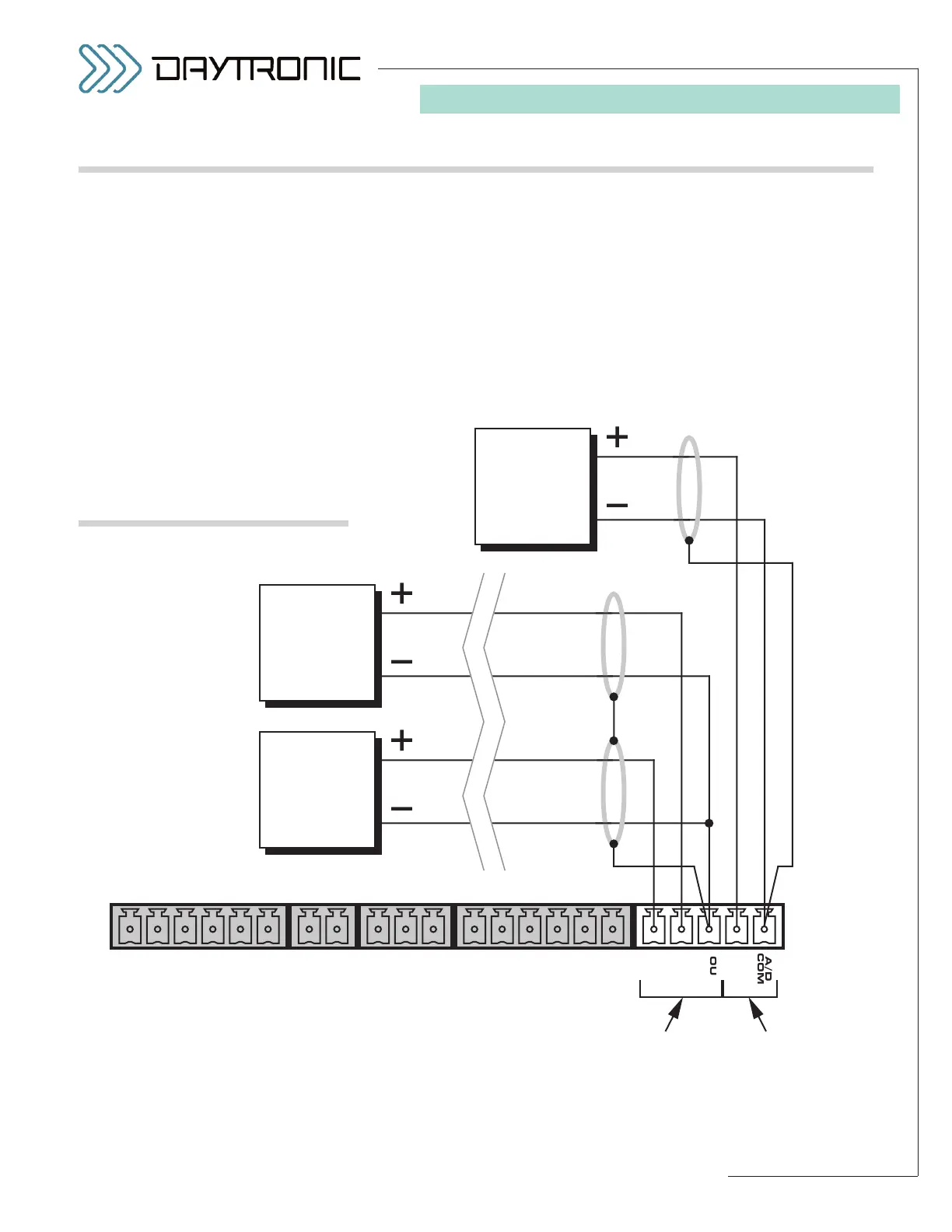
2. CONNECTIONS
Fig. 9
Analog Output Connections
The 3000PLUS produces three analog outputs:
• Channel 3 (VOLTS)—represents the instrument’s
“auxiliary” DAC output (Channel 2) as
scaled volt-
age.
As such, this output may be set to a full scale
of either
±5 or ±10 VDC (1) during meter configura-
tion (Sections 3 and 4); (2) during run-time via the
Configurator’s “Live Output Window” (Section 4); or
(3) by direct application of the
ANALOG VOLTAGE
FULL SCALE (AVV)
command (Appendix A).
• 4-20 mA Output—represents the instrument’s “auxil-
iary” DAC output (Channel 2) as an industry stan-
dard
4-20 mA process signal
• 5D64 Output—represents the “raw” (unscaled)
±5-VDC output of the installed 5D64 conditioner
module (prior to A/D conversion by the 3000PLUS).
Fig. 9 shows how A/D Cards, dataloggers, recorders,
oscilloscopes, and other external devices can connect
to these outputs. Each output is single-ended, and
returns to the appropriate COMMON pin, to which the
respective cable shield should also be tied.
2.D ANALOG OUTPUT CONNECTIONS