TTL-LEVEL LOGIC INPUTS
The 3000PLUS meter’s rear connector has terminals for
the four “positive-true” logic-level inputs shown in Fig.
10.a, below*:
•
HOLD (“HLD”) — when at the Logic 1 (+ 5 V) level,
will cause the reading of the “auxiliary” DAC output
(Channel 2) to be
held (see Section 5.C for details)
•
PEAK (“PEK”) — when at the Logic 1 (+ 5 V) level,
will enable
peak capture for Channel 2 (Section 5.B)
•
TARE (“TAR) — when at the Logic 1 (+ 5 V) level, will
apply a
tare offset to Channel 2, initially forcing it to
the existing
tared output value (Section 5.D)
•
RELEASE LATCH (“RLS LAT”) — when at the Logic
1
(+ 5 V) level, will release (“unlatch”) any and all
currently
latched limits and their respective indica-
tors and relays (Section 5.E)
NOTE: These inputs must be continuously true for their
respective functions to be maintained. Thus, for exam-
ple, if TAR is only
momentarily set to Logic 1, the result-
ing tare offset will be immediately removed from the
Channel 2 reading on return of the TAR input to
Logic 0.
This also means that, as long as it is held at
Logic 1, the
RELEASE LATCH input will continuously defeat the
latching of any subsequent limit alarms.
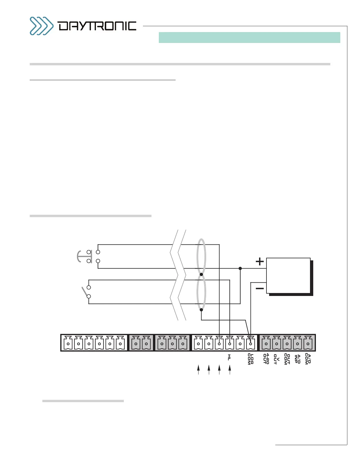
Fig. 10.a shows how the “PEK” and “HLD” inputs can be
independently applied to the 3000PLUS instrument by
means of a normally open push button and contact
switch (respectively), powered by an external supply of
nominal 5-24 VDC. Similar connections can be made
2.E LOGIC I/O CONNECTIONS
* For all four inputs, the Logic 1 state is represented by nominal 5
VDC, and is the “true” state (indicated by the
name of the input);
the
Logic 0 state is represented by nominal 0 VDC, and is the
“false” state. Thus, for example, when the “PEK” input is at
Logic 1, peak capture is enabled. Logic inputs may be gener-
ated directly from dry contacts (switches, relays, etc.), as in Fig.
10.a, or from solid-state logic systems, as in Fig. 10.b. All inputs
assume the
Logic 0 state in the absence of any connection.
Fig. 10
3000PLUS Logic I/O Connections
Fig. 10.a
Logic Inputs with
Switch Closure,
Using External Supply