3KP64 - 2.3
3000PLUS WITH 5D64 INSTRUCTION MANUAL V. SB.2
Daytronic Corporation
2211 Arbor Blvd. Dayton, OH 45439 • (800) 668-4745
Tel: (937) 293-2566 • Fax: (937) 293-2586 • www.daytronic.com
2. CONNECTIONS
is to be used with a cable of under 20 feet in length (or
under 0.1Ω resistance). In this case, the +SENSE and
–SENSE lines are tied to the corresponding EXCITA-
TION lines
at the 5D64 CONNECTOR. The 5-wire
cabling shown in Fig. 8.d is to be used when the cable
is 20 feet or longer, or when fine wire is used. In this
case, the +SENSE and –SENSE lines are tied to the cor-
responding EXCITATION lines
at the transducer.
When connecting to an external potentiometer, note
that the –SIGNAL line should be tied to –EXCITATION
(Terminal 6) when the potentiometer is
zero to full scale
and to SIGNAL COMMON (Terminal 7) when the poten-
tiometer is
zero center.
[NOT USED]
–SIGNAL
SIG. COMMON
–EXCITATION
–SENSE
+SENSE
+EXCITATION
SHIELD*
10
9
8
7
6
5
4
3
2
1
+SIGNAL
*
(NOT ISOLATED; connects
internally to CHASSIS GROUND)
[FOR FUTURE USE]
Analog
Signal
Source
Reg. Power
Supply
(if required)
Add ground for
floating inputs
5D64 Module
SCREW TERMINAL BLOCK
PLUGGED INTO TRANSDUCER
CONNECTOR (see Fig. 3)
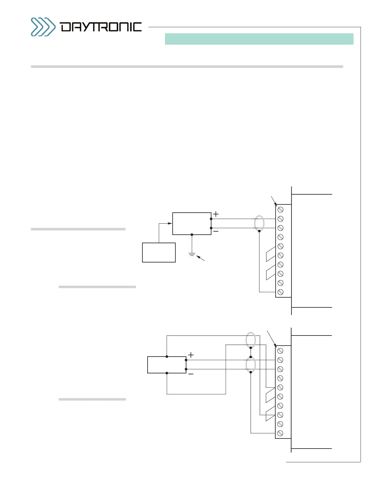
Fig. 8
Model 5D64
Transducer Connections
Fig. 8.a
General 2-Wire Cabling
(external excitation)
[NOT USED]
–SIGNAL
SIG. COMMON
–EXCITATION
–SENSE
+SENSE
+EXCITATION
SHIELD*
10
9
8
7
6
5
4
3
2
1
+SIGNAL
*
(NOT ISOLATED; connects
internally to CHASSIS GROUND)
[FOR FUTURE USE]
DC-to-DC
LVDT
5D64 Module
SCREW TERMINAL BLOCK
PLUGGED INTO TRANSDUCER
CONNECTOR (see Fig. 3)
Fig. 8.b
4-Wire Cabling
to DC-to-DC LVDT
Each wire or jumper of the transducer cable is to be
firmly secured to the appropriate screw terminal of the
terminal block that plugs into the installed 5D64’s 10-pin
TRANSDUCER CONNECTOR.
2-wire cabling for a
general analog source that sup-
plies its own excitation is given in Fig. 8.a. Note that a
floating (ungrounded) input is to be grounded at the site
of the signal source
, and not at the conditioner connec-
tor. Fig. 8.b shows typical wiring for a
DC-to-DC LVDT,
using the 10-VDC excitation provided by the 5D64. In
most cases, the ±SENSE lines should be tied to the cor-
responding EXCITATION lines
at the 5D64 CONNEC-
TOR
, as shown, regardless of cable length.
Connections to an
external potentiometer are given
in Figs. 8.c and 8.d. The 3-wire cabling shown in Fig. 8.c
2.C TRANSDUCER CONNECTIONS