3KP64 - 1.6
3000PLUS WITH 5D64 INSTRUCTION MANUAL V. SB.2
Daytronic Corporation
2211 Arbor Blvd. Dayton, OH 45439 • (800) 668-4745
Tel: (937) 293-2566 • Fax: (937) 293-2586 • www.daytronic.com
1. INTRODUCTION
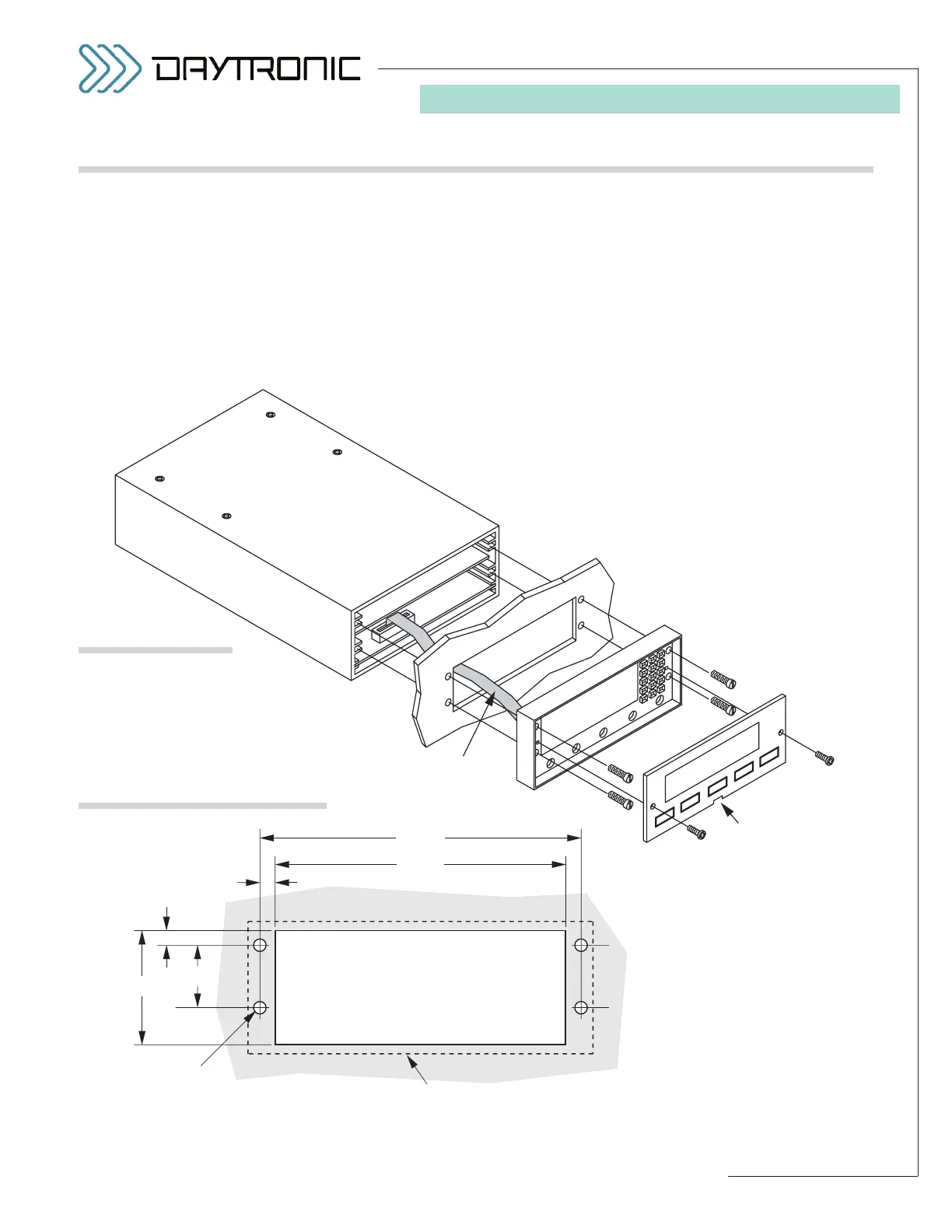
You can easily mount the 3000PLUS instrument in your
own precut panel. See Fig. 5, below, for appropriate
cutout and hole dimensions. PANEL THICKNESS
SHOULD NOT EXCEED 1/8 INCH. The mounting proce-
dure is as follows:
1. Remove the two front-panel screws (“A” in Fig. 4).
2. Remove the front panel by inserting the tip of a flat
screwdriver into the notch at the bottom of the
panel and gently prying it out of the bezel case.
Front Panel
Front Bezel
Display
Cable
Panel Notch
User's Panel with Cutout
and Mounting Holes
(see Fig. 5)
A
B
4.060 "
3.700 "
0.180 "
0.200 "
0.156" dia.
Edge of 3000PLUS instrument
1.45 "
0.775 "
Fig. 4
3000PLUS
Panel Mounting
Fig. 5
Panel Cutout Dimensions
3. Remove the four screws (“B”) holding the bezel to
the instrument housing.
NOTE: YOU DO NOT NEED TO DISCONNECT THE
INTERNAL DISPLAY CABLE.
4. Hold the instrument housing behind the panel and
pass the bezel through the cutout (with cable
attached).
5. Reattach the bezel to the housing, using the same
four half-inch screws (“B”). The ribbon cable
should fold into the space between the top of the
instrument and the upper circuit board.
6. Snap the front panel back into the bezel case, and
reinstall the two quarter-inch front-panel screws
(“A”).
1.C PANEL MOUNTING