DB ELETTRONICA TELECOMUNICAZIONI S.p.A.
PM 1000 – 1 kW FM Broadcasting Transmitter - USER’S MANUAL
18 /101
3.3.2 MEASURES / CONTROLS SECTION
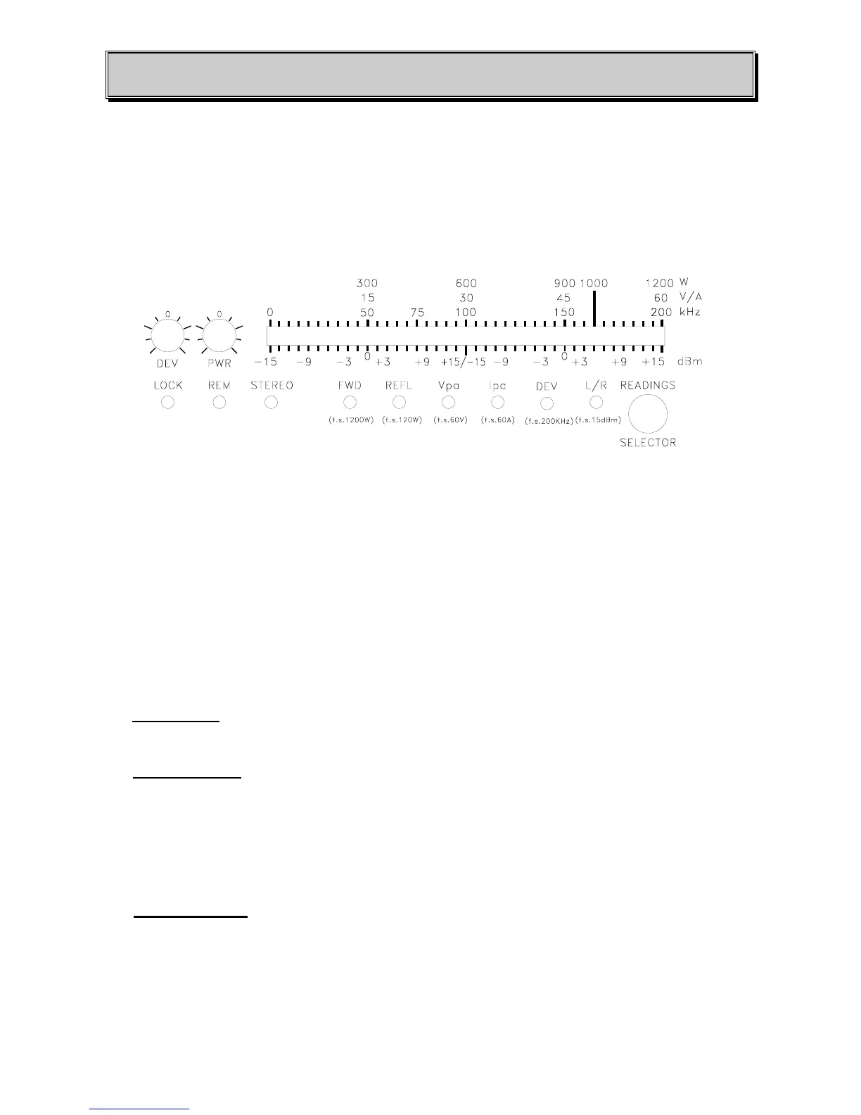
On the front panel (Fig. 1.1) there is a 40 leds meter bar (see Fig. 1.1) which displays the most
important parameters of the transmitter. The push-button labelled “MEASURE SELECT” selects
the measure type, as indicated by one of the leds below the bar.
You can visualise 6 parameters:
- FWD measure displays the output power (f.s. 1200W).
- REFL measure displays the reflected power (f.s. 120W).
- Vpa measure displays the bias of final transistors (f.s. 60V).
- Ipa measure displays the absorbed current of final transistors (f.s. 60A).
- DEV measure displays the peak deviation of modulated carrier (f.s. 200KHz).
- L/R measure displays the input audio level. (the meter bar is split in two parts, one for each
audio channel).
⇒ “LOCK” led:
shows the correct lock of the frequency synthesis circuit (PLL) on the modulator
board.
⇒ “STEREO” led:
shows the use of the internal stereo generator board (if present). This led is
related to the switch (Fig. 1.1) labelled “STEREO/MONO” which allows selection of the type of
signal to be modulated. The mono signal is obtained by a semi-sum of the left and the right
signals for the PM1000. If the internal stereo generator board is not present, the switch
mentioned above and the corresponding LED are unused.
⇒ “REMOTE” led:
indicates if the operation of the transmitter can be remote controlled. This
selection is made using the switch “ REMOTE/MANUAL”. This switch and the relative led will
be unused if the transmitter is not equipped with the remote control board option.