INDEX
BRIEF OPERATING
INSTRUCTIONS
3
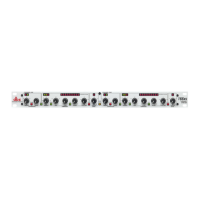
Front Panel
3
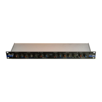
Rear Panel
4
INTRODUCTION
5
More
About Separate Level Detector Access
5
More
About
Over
Easy''’^ Compression
5
SIGNAL CONNECTIONS
6
Input
Connection
6
Level Detector Input Connection
6
Output
Connection
7
Grounding
7
Stereo Coupler Cable
7
Input Impedance &
Terminations
7
OPERATION Sr^^lWTI01^ 8
Compression
Control 8
Threshold Adjustment & LEO Indicators
8
Auto Switch & Auto Attack/Release
LED Indicator 8
Attack Rate & Release Rate
Controls 8
Where To Set Attack &
Release Controls 8
Meter Calibration & Use
8
Use
of an Equalizer in the Level Detector Circuit
for Frequency Weighted 8
Compression, De*esslng, or
Increasing Sustain
Use of a
Filter
in
the Level Detector Circuit 9
Use of a
Time Delay Line in the Signal Path but not in the
Level Detector 9
Circuit
for Zero or Negative Attack & Release
Times
The
165
As A Line Amplifier
9
SPECIFICATIONS
10
dbx
PRODUCT WARRANTY
&
FACTORY SERVICE 10
BLOCK DIAGRAM
11
SCHEMATIC
12
dbx GLOSSARY
I
WARNING: TO
PREVENT FIRE OR SHOCK HAZARD,
DO NOT EXPOSE THIS
APPLIANCE TO RAIN OR MOISTURE.