SIGNAL
CONNECTIONS
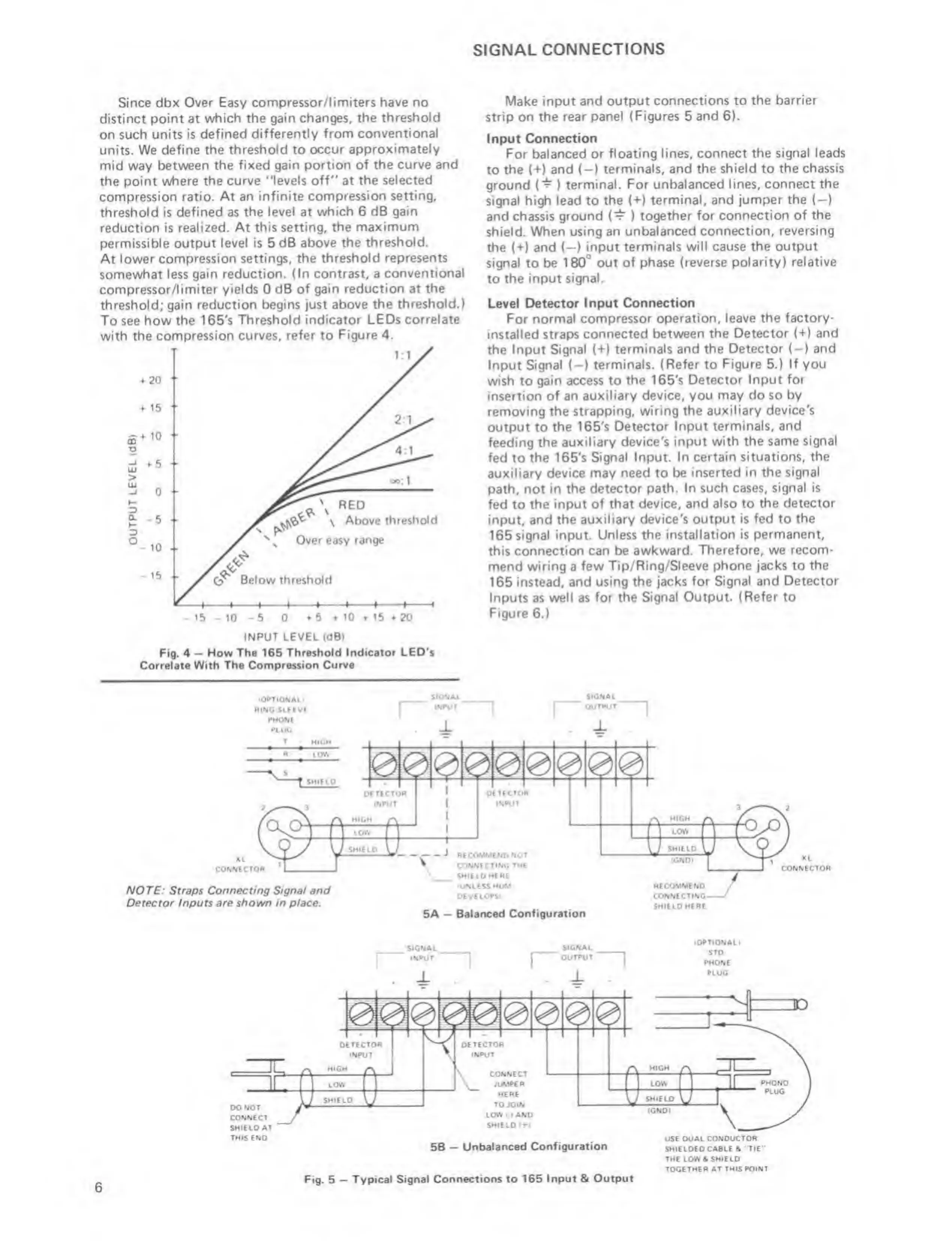
Since dbx Over Easy
compressor/limiters have no
distinct
point at which
the
gain
changes, the threshold
on
such units is defined
differently from conventional
units.
We define
the threshold
to
occur
approximately
mid way
between the fixed gain portion of
the curve and
the point
where the curve "levels off" at
the selected
compression ratio. At an infinite
compression setting,
threshold Is defined as
the level
at
which 6 d6 gain
reduction is
realized. At this setting,
the maximum
permissible output level is 5dB
above the threshold.
At lower compression
settings, the threshold
represents
somewhat
less gain reduction.
(In contrast,
a
conventional
compressor/limiter yields 0
dB of gain
reduction
at
the
threshold;
gain reduction begins just
above the threshold.)
To
see
how the 1 65's
Threshold indicator LEDs
correlate
with the
compression curves, refer to
Figure 4.
INPUT
LEVEL
(dB)
Fig, 4
-
How Th« 165
Threshold Indicator LEO*s
Correlate
With The Compression Curve
Make input and output
connections to the barrier
strip on the
rear panel (Figures 5 and 6).
Input
Connection
For balanced or floating lines,
connect the signal leads
to
the
(+)
and
(—
)
terminals, and the shield to
the chassis
ground
(*^
)
terminal.
For
unbalanced
lines, connect the
signal
high lead
to
the
(+)
terminal, and jumper the (—
)
and chassis ground
)
together for connection of the
shield. When
using an unbalanced
connection, reversing
the
(+)
and
(—
)
input terminals will
cause the output
signal
to be
180°
out of phase
(reverse polarity) relative
to
the input
signal.
Level Detector Input
Connection
For normal
compressor operation, leave
the
factory*
installed
straps connected
between the Detector
(*f*)
and
the Input Signal (+)
terminals and the
Detector (-) and
Input
Signal (—
)
terminals.
(Refer
to
Figure
5.)
If you
wish to
gain access to
the
165's
Detector Input for
insertion of
an auxiliary device, you
may
do
so by
removing the strapping,
wiring the auxiliary
device's
output to the
165'$
Detector Input
terminals, and
feeding
the auxiliary
device's input with the
same signal
fed
to
the 165's
Signal Input. In certain
situations, the
auxiliary
device may need to be inserted
in the signal
path, not
in the detector
path. In such cases, signal is
fed to the input of
that device, and also to
the detector
input,
and the auxiliary device's
output is fed to
the
165
signal input.
Unless the installation is permanent,
this connection can be
awkward. Therefore, we
recom-
mend
wiring
a
few Tip/Ring/Sleeve phone
jacks
to
the
165 instead,
and using the jacks
for Signal and Detector
Inputs as
well as for
the
Signal
Output. (Refer to
Figure 6.)
CO»TlONAi>
RkMG SLfCVl
nvc
T
HIGH
tow
Sh»KD
SKMAL
WAUT
SIGNAL
ouTAur
J.
MriCtOA
INAtjT
XL
CONNCCTOR
OCTECtO*
INAur
NOT£: Straps Connecting Signal end
Detector inputs
are shown
in
place.
RCCOMMCND
M>t
CONMCTtNC THE
SMIEiO M(«(
«UNlESSHUM
DEVEiOASi
5A
—
Balanced ConfiguraUon
RECOMME
NO
CONNECTING-
SHIE
to
MERE
XL
CONNECTOR
SIGNAC
Signal
(OAllONAtl
STQ
RHONE
AtUG
OONOr
CONNECT
SHIELD
AT
THIS END
5B
—
Unbalanced
Configuration
USE DUAL CONDUCTOR
SHIELDED CA»LE S
'TIE
'
THE LOW A SHIELD
TOGETHER
AT THIS POINT
6
Fig.
5
“
Typical
Signal Connections to 165 Input &
Output
 Loading...