OPTION AU
IPO A PEED TO AUkILIAAV
INPUT
MVLT
SIGNAC PPtOCeSSOAl
F
19
.
6
“
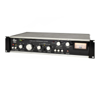
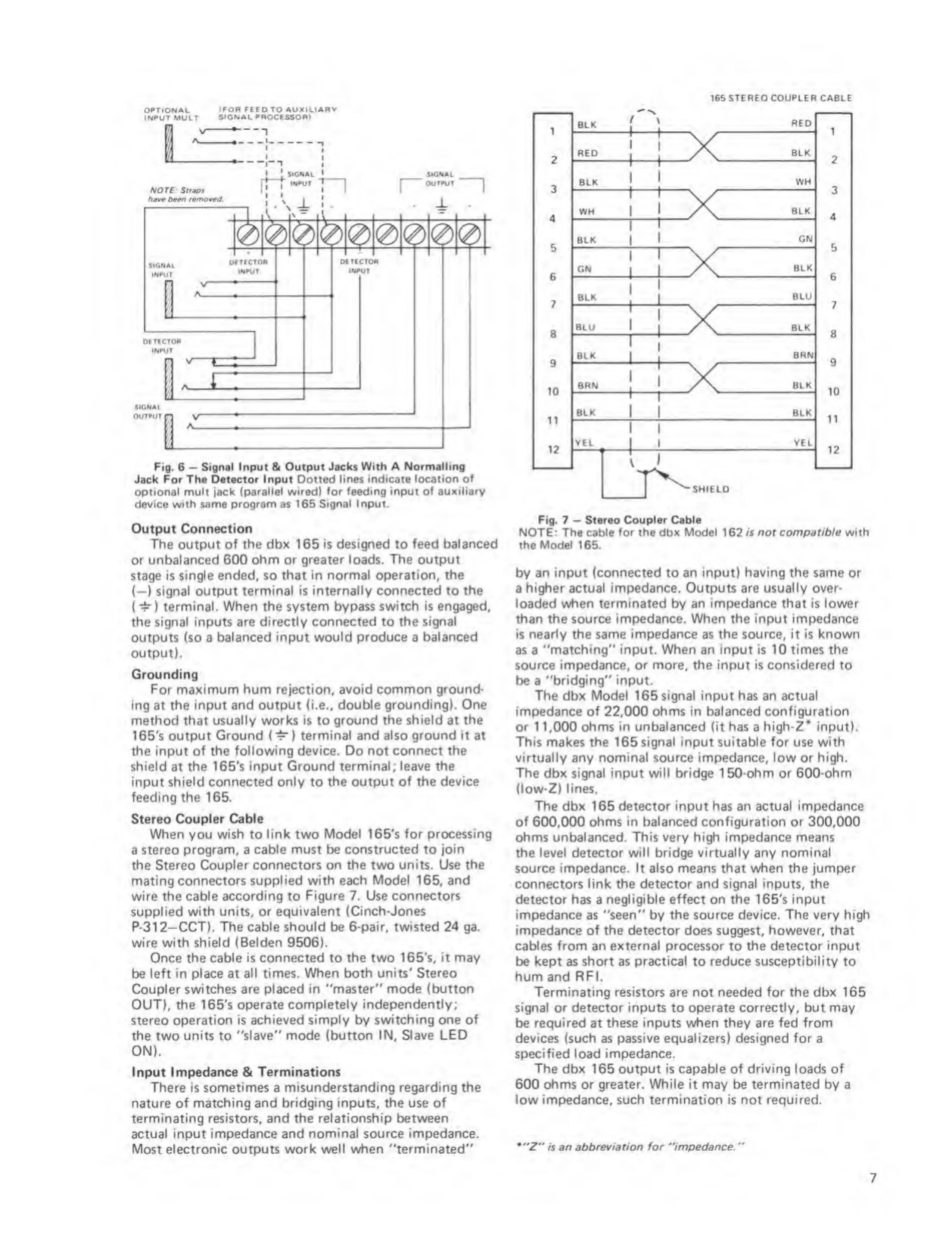
Signal Input & Output Jacks With A
Normalling
Jack For The Datactor Input Dotted
lines indicate location of
optional mult jack (parallel wired) for faadirtg input
of auxiliary
device with same program as 165
Signal Input.
Output Connection
The output of
the dbx
165
is designed
to
feed balanced
or unbalanced 600
ohm
or
greater loads. The output
stage is
single ended,
$0
that in normal operation, the
(—
)
signal output terminal is internally connected to
the
(
^ )
terminal. When the system bypass
switch is engaged,
the signal inputs are directly connected
to
the signal
outputs (so a
balanced input would produce a
balanced
output).
Grounding
For maximum hum rejection, avoid common ground*
ing at the input and output (i.e.,
double grounding). One
method
that
usually works is
to
ground the shield at the
16S's output
Ground
(‘^
)
terminal and also ground it
at
the input of the following device. Do not connect the
shield
at
the 165's input Ground
terminal
;
leave the
input
shield connected only
to
the output of the device
feeding the 165.
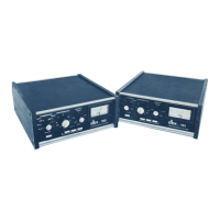
Stereo Coupler Cable
When you
wish
to
link
two
Model
165's
for processing
a
stereo program, a cable must be constructed to join
the Stereo Coupler connectors on the two units. Use
the
mating connectors
supplied with each Model
165,
and
wire
the cable according
to
Figure 7. Use connectors
supplied with units, or equivalent (Cinch-Jones
P-312—CCT). The cable should be
6-pair, twisted
24 ga.
wire with shield
(Belden
9506).
Once the cable is connected to the two 165's, it
may
be
left in place at all times.
When both units' Stereo
Coupler switches are placed in
''master" mode (button
OUT), the 165's operate
completely Independently;
stereo
operation is achieved simply by switching
one
of
the
two
units
to
"slave" mode (button IN,
Slave LED
ON).
Input Impedance 6c Terminations
There is
sometimes
a
misunderstanding regarding the
nature of matching and bridging inputs, the use of
terminating resistors, and
the relationship between
actual input impedance and nominal source impedance.
Most electronic outputs work well when "terminated"
1
2
3
4
5
6
7
B
9
10
n
12
BLK
RED
STEREO COUPLER CABLE
RED
X
SHIELD
BLK
BLK
1
‘
1
—
t—
1
WH
WH
1
1
1
1
IX
BLK
BLK
1
1
1
GN
GN
1
1
1
IX
BLK
BLK
1
j
BLU
GLU
1
1
1
BLK
BLK
1
1
1
BRN
BRN
1
1
1
BLK
BLK
1
!
1
BLK
VtL
1
-1-
1
i
YEL
1
2
3
4
5
6
7
8
9
10
11
12
Fig.
7
“
$t«r60 Coupltr Cable
NOTE: The cable for the dbx Model 162 is not comp9tib/e with
the
Model
1 65.
by an input
(connected
to an input)
having the same
or
a
higher actual impedance. Outputs are usually over-
loaded when terminated by an impedance
that
is lower
than the source impedance. When the input impedance
is nearly the same impedance as the source, it is known
as a "matching" input When an input is 10 times the
source impedance, or more, the input is considered
to
be a "bridging" input.
The dbx Model
165 signal
input has an actual
impedance of
22,000
ohms in balanced configuration
or 1 1,000 ohms in unbalanced (it has a
high-Z*
input).
This makes the
165
signal
input
suitable for
use
with
virtually any nominal source impedance, low or high.
The dbx signal input will bridge 150-ohm or 600-ohm
(low-Z) lines.
The dbx 165 detector input has an actual impedance
of
600.000
ohms in balanced configuration or 300,000
ohms unbalanced.
This very high impedance means
the level detector will bridge virtually any nominal
source impedance. It also means that when the jumper
connectors link the detector and signal inputs, the
detector has a
negligible
effect on the 165's input
impedance
as
"seen"
by
the source device. The very high
impedance of the detector
does
suggest, however, that
cables from an external processor to the detector input
be kept as
short
as
practical
to reduce susceptibility to
hum and RF I.
Terminating resistors are not needed for the dbx 165
signal or detector inputs
to
operate correctly, but may
be
required at these inputs when they are fed from
devices (such as
passive equalizers) designed for
a
specified load impedance.
The dbx
165
output
is
capable of driving loads of
600 ohms or greater. While it may be terminated by a
low impedance, such termination is not required.
•"Z" f$ 90 sbbrevisrion for "imped9nce.
“
7
 Loading...