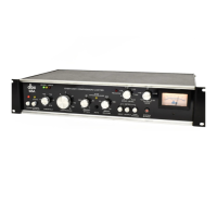
BRIEF OPERATING INSTRUCTIONS
Fig.
1
—
Front Pan^l
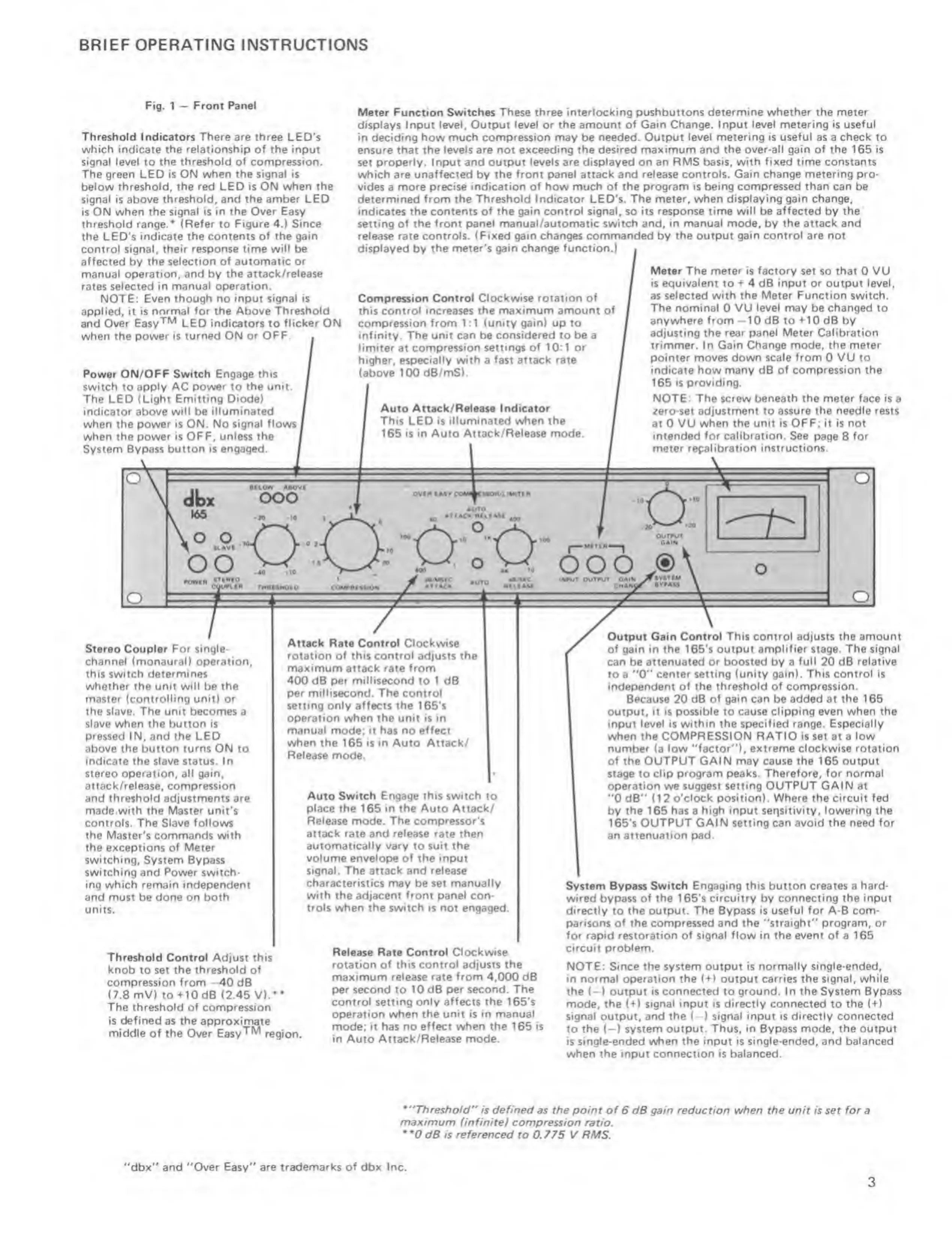
Threshold Indicators There are three LED's
which indicate the relationship of the input
signal level to the
threshold of
compression.
The green
LED
is ON when the signal is
below threshold, the red LED is ON when
the
signal is above
threshold,
and
the amber
LED
is ON
when the signal is in the Over Easy
threshold range.* (Refer to
Figure
4.)
Since
the
LED's
indicate the contents of the gain
control signal, their response time
will
be
affected
by
the
selection of automatic or
manual operation, and
by
the attack /re I ease
rates selected in
manual operation.
NOTE:
Everi though no input signal is
applied, it is normal for the Above
Threshold
and Over Easy^^ LED indicators
to
flicker ON
when the power is turned ON or
OFF.
Power ON/OPF Switch Engage
this
switch CO
apply
AC
power
to
the unit.
The LED (Light Emitting
Diode)
indicator above
will
be
illuminated
when the
power is ON,
No
signal flows
when Che power Is OFF. unless the
System Bypass
button is engaged.
Meter Function Switches These three interlocking pushbuttons determine
whether the
meter
displays Input
level.
Output
level or theamourtt of Gain Change. Input level metering is useful
in deciding
how much compression may
be
needed. Output level metering is useful as a check to
ensure that the levels are not exceeding the desired
maximum
and
the over-all gain of the 165 is
set
properly. Input and output levels are displayed on an RMS basis, with
fixed
time constants
which are
unaffected
by
the front panel
attack and
release controls. Gain change metering pro-
vides
a
more precise indication of how much of the program is being compressed
than
can be
determined
from the Threshold Indicator
LED's.
The meter, when displaying gain change,
indicates the contents
of
the gain control
signal,
so its response
time will
be
affected
by
the
setting of the front panel manual /automatic switch and, in manual mode, by
the
attack and
release
rate
controls. (Fixed gain changes commanded
by
the output gain control are not
displayed
by
the meter's gain change function.)
MbOVr
MOvl
ooo
OO
W.
Compression
Control Clockwise rotation of
this
control increases the maximum amount
of
compression from 1 :1 (unity
gain)
up to
infinity. The unit can be considered to be a
limiter at
compression settings of 10:1 or
higher, especially with a
fast
attack
rate
(above 100 d6/mS).
Auto
Attack/ Release Indicator
This
LED
is illuminated when the
165 is in Auto Atcack/Release mode.
own luvc
Meter The meter is factory
set so
that
0 VU
is
equivalent
to 4 dB
input or
output level,
as
selected with the Meter Function switch.
The nominal 0 VU
level
may be
changed
to
anywhere from -10 dB
to
+10 dB
by
adjusting the rear
panel
Meter
Calibration
trimmer, In
Gain Change mode, the meter
pointer moves down
scale
from 0 VU to
indicate how
many
dB
of compression the
165 is providing.
NOTE:
The screw beneath the meter face is
a
zero-set adjustment to
assure the needle rests
at 0 VU
when the unit is OFF; it is not
intended for calibration. See
page
8
for
meter repahbration instructions.
t%on
Auro
AttACH MUAM
TH«a$HOtO
'O:
°-
0
"
400
^
13
ooo
,®
OAi«<
Jri»s*CM
CWAI^r
A^»A»
«<#ut OOfAvrf
Stereo Coupler For single*
channel (monaural) operation,
this switch determines
whether the unit will be the
master (controlling unit)
or
the slave. The
unit becomes a
slave when the button is
pressed
IN, and
the
LEO
above the button turns ON to
ir>diC3te the
slave
status. In
stereo operation, all gain,
attack/release, compression
and threshold adjustments are
made with the Master unit’s
controls. The Slave follows
the
Master's commands
with
the exceptions of Meter
switching.
System Bypass
switching and Power switch-
ing which remain independent
and must be done on both
units.
Attack
Rate Control Clockwise
rotation of this control adjusts the
maximum attack rate from
400
dB
per millisecond
to 1 dB
per millisecond. The control
setting
only affects
the I65's
operation when the unit is in
manual
mode; it has no
effect
when the 166 is in
Auto
Attack/
Release mode.
Auto Switch Engage this switch to
place
the 165 in
the
Auto Attack/
Release
mode.
The compressor's
attack rate and release rate then
automatically vary
to
suit the
volume envelope of the Input
signal. The attack
and
release
characteristics may
be set
manually
with
the adjacent
front panel
con-
trols when the switch is not engaged.
Output Gain
Control This control
adjusts
the
amount
of gain
in
the
165'$
output amplifier
stage.
The signal
can be
attenuated or boosted
by
a full
20
dB relative
to a
"0"
center
setting
(unity
gain).
This control
Is
independent of the threshold of compression.
Because
20
dB
of
gain
can
be added at the 165
output, it is
possible
to cause
clipping even when the
input level is within the specified range. Especially
when the COMPRESSION RATIO is
set at a
low
number
fa
low ''factor*'), extreme
clockwise
rotation
of
the
OUTPUT
GAIN may cause
the
165 output
stage to
clip program peaks. Therefore, for normal
operation
we suggest
setting OUTPUT GAIN
at
"0
dB'* f12
o'clock position). Where the circuit fed
by the 165 has a
high
input sensitivity,
lowering the
1€5's
OUTPUT GAIN setting can avoid the need for
an
attenuation
pad.
Threshold Control
Adjust this
knob to set the threshold of
compression from —40
dB
(7.8 mV)
to+IOdB
(2.46
V).**
The threshold
of compression
is
defined
as the approximate
middle
of
the
Over Easy"**^ region.
Release Rate Control Clockwise
rotation of this
control
adjusts
the
maximum release rate from
4,000
dB
per second to 10 dB
per
second. The
control setting only affects the
165's
operation when
the unit
is
in manual
mode;
it has no effect when the 165 is
in Auto
Attack/Release
mode.
System Bypass Switch Engaging this button creates a
hard*
wired
bypass
of the
165'$
circuitry
by
connecting the input
directly
to the output. The Bypass is
useful for
A-B com-
parisons of the
compressed and the ''straight" program, or
for rapid restoration of signal flow tn the event of a 165
circuit
problem.
NOTE: Since the system output is normally single-ended,
in normal operation the
(
+
1 output carries the signal,
while
the {-)
output
is connected
to
ground. In the System
Bypass
mode, the (+) signal input is directly connected
to
the (+)
signal
output, and
the (-) signal input is directly
connected
to
the
(—
)
system output. Thus, in Bypass mode, the output
is single-ended when the input is single-ended, and
balanced
when the
input
connection
is
balanced.
*"Thre$^ofd" is defined
as
the
point of 6 dB gain reduction when the unit is set for a
maximum
(infinite} compression ratio.
dB is referenced
to 0.775 V RMS.
'’dbx" and "Over
Easy"
are
trademarks of
dbx
Inc.
3
 Loading...