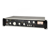
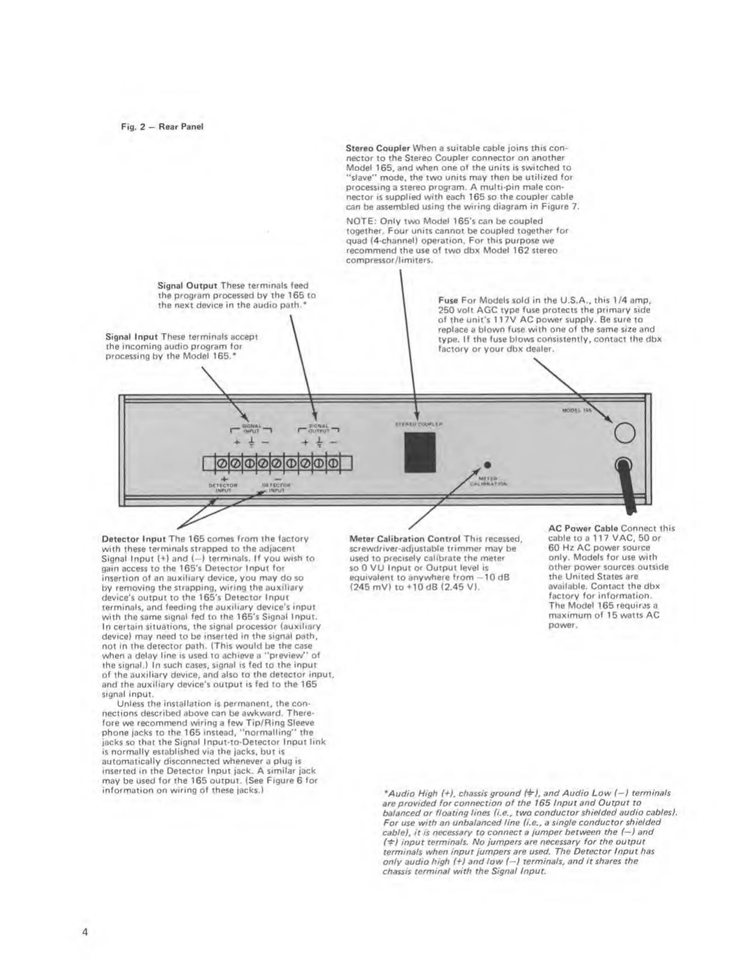
Fig.
2
“
Rear
Panel
Stereo Coupler
When
a
suitable cable joins this con-
nector to
the Stereo Coupler connector on another
Model
165,
and when one of the units is switched to
"slave"
mode,
the
two
units
may
then
be
utilized for
processing
a
stereo program. A multi-pin male con-
nector is supplied with each 165 so the
coupler cable
can be
assembled using the wiring diagram in Figure 7.
NOT£:
Only
two
Model
165's
can
be
coupled
together. Four units cannot be coupled
together for
quad (4-channeO
operation. For this purpose
we
recommend the
use
of
two
dbx Model 162 stereo
compfessor/l i miters.
Signal Output
These terminals feed
the program processed
by
the 165 to
the next device in the audio path.*
Signal Input These terminals accept
the incoming audio
program for
processing
by
the Model
165.'
Fuse For Models sold in the U.S.A..
this
1 /4 amp,
250
volt
AGC
type fuse protects the primary side
of the unit's 1 1 7V AC
power supply.
Be
sure
to
replace
a
blown fuse with one of the same size and
type.
If the fuse blows consistently, contact the dbx
factory
or your dbx
dealer.
OUTMjT
stiMocounta
*
^
1
MOOlb
iM
o
lOIOKDIOIOIOIOI
(MTICTM
(•UT
MMCTCM
__ i<#ur
Detector Input
The
165 comes
from the factory
with these terminals
strapped
to
the adjacent
Signal
Input
(*>’)
and (—) terminals. If you wish to
gain
access
to the I65’s Detector
Input for
insertion of an
auxiliary device, you may
do so
by
removing the strapping, wiring the auxiliary
device's output to the 165's
Detector Input
terminals, and
feeding the auxiliary device’s input
with the same signal fed to the 165's Signal
Input.
In certain situations,
the signal processor (auxiliery
device)
may
need
to be
inserted in the signal path,
not in the detector path. (This
would
be
the
case
when
a
delay line is used to achieve a "preview"
of
the
signal.)
In
such
cases,
signal is fed
to
the input
of the auxiliary device, and
also
to
the detector input,
and the
auxiliary device’s
output
is fed
to
the 165
signal input.
Unless the installation is permanent, the con-
Meter Calibration
Control This recessed,
screwdriver
-adjust
able trimmer may
ba
used to precisely
calibrate
the
meter
so 0
VU Input or Output level is
equivalent
to
anywhere from
-
1 0 dB
(245 mV) to+10dB (2.45 V).
AC Power Cable Connect
this
cable
to a
117 VAC. 50 or
60 Hz AC power source
only. Models for use with
other power
sources outside
the United States are
available.
Contact
the dbx
fectory for information.
The
Model
165
requir^is
a
maximum of
15
watts AC
power.
nections described
above
can be
awkward. There-
fore
we
recommend wiring e few Tip/Ring Sleeve
phone jacks to the 165
instead, "normalling" the
jacks so
that the Signal Input-to-Detector Input link
is normally established via the jacks, but is
automatically disconnected
whenever
a
plug is
inserted
in
the Detector Input jack. A similar jack
may
be
used for the 165 output. (See Figure 6
for
information on wiring of these jacks.)
Mud/o Mg/t
(+),
chassis
ground and Audio Low
(-i
eermina/s
are provided
for connection of the 165 Input and Output to
balanced or floating lines U.e., two
conductor shielded audio cables).
For use with an unbalanced
line
f/.e„ a
single conductor shielded
cable), it is
necessary to connect a jumper between the
i^)
and
(‘t)
input terminals. No
jumpers are necessary for the output
terminals when
input jumpers are used. The Detector Input
has
only
audio high
{^}
and low (—) terminals, and it
shares the
chassis terminal with
the Signal Input
4
 Loading...