11
FIG. 05
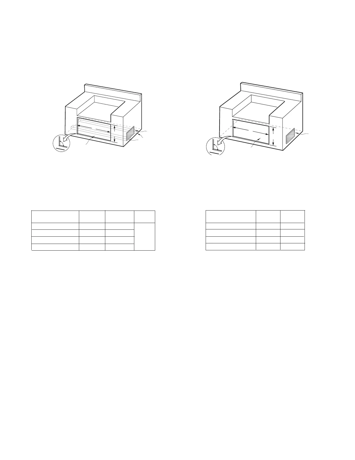
Access Doors
Cutout dimensions
A
90º
B
Vent*
Cutout for Access Doors
MODEL NUMBER A B
+0,1/8 +1/8,0
ADN120x48 46” 20”
ADN120x36 34” 20”
ADN120x30 28” 20”
ADN120x24 22” 20”
A
90º
B
Vent*
Optimal support
location**
Access Drawers
Cutout dimensions
NOTE: The cutout of each corner should be 90
º
angle in order for the access
drawers to fit properly.
* The enclosure should have ventilation holes to prevent gas build-up in the
event of a leak. Refer to ANSI Z21.58 Standard for Outdoor Cooking Gas
Appliances, Section 1.7 Enclosures For Self Contained LP-Gas Supply Systems.
** For proper support and drawer operation, insure that support boards are
installed per Installation Guide instructions
To order access drawers or doors, please call DCS Customer Care at 1.888.936.7872 for DCS Dealer in your area.
MODEL NUMBER A B C
+0,1/8 +1/8,0
ADR2 48 46” 20”
ADR236 34” 20”
ADR230 28” 20”
ADR224 22” 20”
24-1/2”
(Min,
All
Models)
NOTE: The cutout of each corner should be 90
º
angle in order
for the access drawers to fit properly.
* The enclosure should have ventilation holes to prevent
gas build-up in the event of a leak. Refer to ANSI Z21.58
Standard for Outdoor Cooking Gas Appliances, Section 1.7
Enclosures For Self Contained LP-Gas Supply Systems.
FIG. 06
INSTALLATION
BUILTIN CONSTRUCTION DETAILS
EN