16
!4 ELECTRICAL CONNECTION
ALL MODELS
RGV2 & RGCV2 MODELS
RDV2 MODELS
IMPORTANT!
●
This range must be connected to the mains
power supply only by a suitably qualified person.
●
This range must be earthed.
●
Always disconnect electric supply cord from the
wall outlet or service disconnect before servicing
this appliance.
●
Observe all governing codes and ordinances
when grounding, in absence of which, observe
National Electrical Code ANSI / NFPA No. 70.
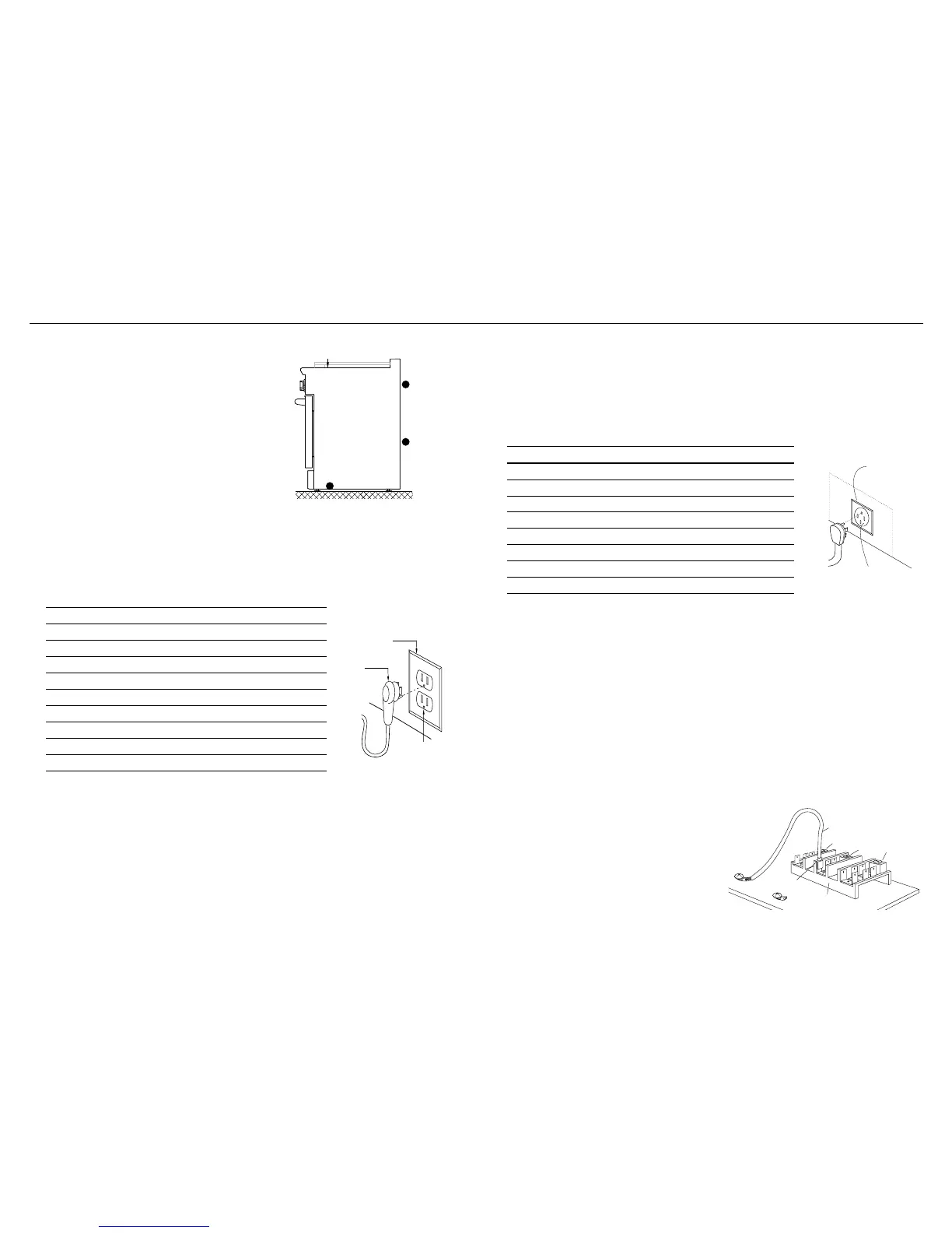
The rating
label is located
on the back of
the range
A wiring
diagram label
is attached to
the back of
the range
Wiring diagrams
are also in the
service summary,
attached to the
inside of the kick
panel
The electrical supply must be a correctly polarized 120 V AC, 60 Hz, single phase circuit
suitable for the maximum current draw of the model, as detailed in the table below.
Please verify your model’s current draw by checking the rating label on the back of the
range.
Required grounding method – RGV2 & RGCV2 MODELS
●
This appliance is factory equipped with a power supply cord with a three-prong
grounding plug (with polarized parallel blades). It must be plugged into a mating
grounding-type receptacle, connected to a correctly polarized 120 volt circuit. If the
circuit does not have a grounding type receptacle, it is the responsibility and obligation
of the installer to have the existing receptacle changed to a properly grounded and
polarized receptacle in accordance with all applicable local codes and ordinances by
a qualified electrician. In the absence of local codes and ordinances, the receptacle
replacement shall be in accordance with the National Electrical Code.
●
IMPORTANT!
The third prong should not, under ANY circumstances, be cut or removed.
The electrical supply must be a correctly polarized 120/240 volt, 3-wire (plus ground),
60 Hz circuit suitable for the maximum current draw of the model, as detailed in the table
below. Please verify your model’s current draw by checking the rating label on the back of
the range.
The power receptacle must be a NEMA 14-50 device to accept the four prong plug supplied
with the unit. The receptacle should be located within the area shown on opposite page.
Required grounding method – RDV2 MODELS
●
This appliance is factory equipped with a power supply cord with a four-prong grounding
plug. It must be plugged into a mating grounding, type receptacle, connected to a correctly
polarized 120/240 volt circuit. If the circuit does not have a grounding type receptacle, it is
the responsibility and obligation of the installer to have the existing receptacle changed to
a properly grounded and polarized receptacle in accordance with all applicable local codes
and ordinances by a qualified electrician. In the absence of local codes and ordinances, the
receptacle replacement shall be in accordance with the National Electrical Code.
●
IMPORTANT!
The fourth prong (round grounding pin) should not, under any circumstances, be cut or
removed.
Connecting to an electrical system utilizing a single conductor for ground and neutral
The range is equipped for use with an electrical supply which uses a separate grounding
conductor (4 wire system). If this range must be connected to an electrical system which
utilizes a single conductor for ground and neutral (3 wire system), the grounding jumper at
the terminal block must be connected. The grounding jumper is located behind the front
kickpanel.
To connect grounding jumper:
●
Disconnect restraining clip holding jumper.
●
Connect green jumper to open terminal on
neutral (white) portion of the terminal block,
as shown
Receptacle Box
Cover Plate
Three Prong
Receptacle
Three
Prong
Plug
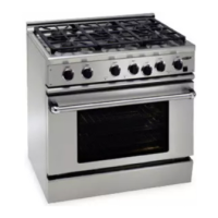
MODEL MAX. CURRENT DRAW CIRCUIT
RGCV2-305 5 A 15 A
RGV2-364GD 8 A 15 A
RGV2-304 5 A 15 A
RGV2-366 5 A 15 A
RGV2-488 9 A 15 A
RGV2-485GD 15 A 15 A
RGV2-486GD 12 A 15 A
RGV2-486GL 12 A 15 A
MODEL MAX. CURRENT DRAW CIRCUIT
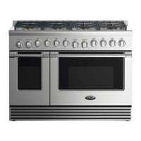
RDV2-305 18 A 30 A
RDV2-304 21 A 30 A
RDV2-364GD 21 A 30 A
RDV2-366 18 A 30 A
RDV2-488 33 A 50 A
RDV2-485GD 40 A 50 A
RDV2-486GD 36 A 50 A
RDV2-486GL 36 A 50 A