9
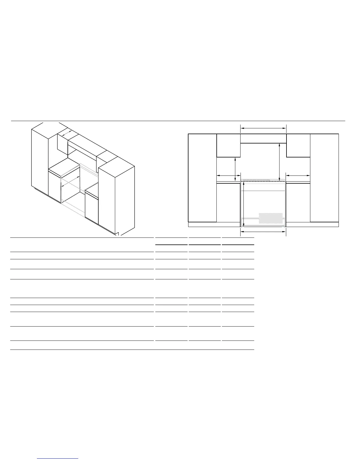
6 CLEARANCE DIMENSIONS - ALL MODELS
CLEARANCE DIMENSIONS
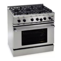
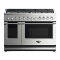
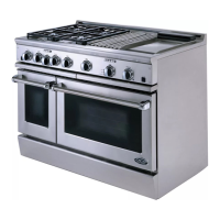
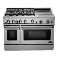
30” MODELS 36” MODELS 48” MODELS
inches (mm) inches (mm) inches (mm)
A
Minimum width of ventilation hood installed above range 30’’ (762) 36’’ (914) 48’’ (1219)
B
Minimum vertical distance between countertop and cabinet extending above
counter
18
’’ (457) 18’’ (457) 18’’ (457)
C
Minimum clearance from left and right edge of range to nearest vertical
combustible surface
12” (305) 12” (305) 12” (305)
D
Minimum clearance from cooking surface to:
- combustible surface centered above the cooking surface
- combustible covering for ventilation hood centered above the cooking surface
- non-combustible surface* centered above the cooking surface
54” (1372)
36” (914)
30’’ (762)
54” (1372)
36” (914)
30’’ (762)
54” (1372)
36” (914)
30’’ (762)
E
Maximum overall depth of overhead cabinetry 13” (330) 13” (330) 13” (330)
F
Width of cabinetry opening 30’’ (762) 36’’ (914) 48’’ (1219)
G
Maximum height from floor to countertop:
- for level counter
- with range levelling legs fully extended
35 3/4” (908)
36 3/4’’ (933)
35 3/4” (908)
36 3/4’’ (933)
35 3/4” (908)
36 3/4’’ (933)
H
Maximum depth from wall to cabinetry face:
- projecting control panel
- flush control panel
25 1/8” (638)
27 11/16”
(703)
25 1/8” (638)
27 11/16”
(703)
25 1/8” (638)
27 11/16”
(703)
* Non-combustible surfaces:as defined in ‘National Fuel Gas Code’ (ANSI Z223.1, Current Edition). Clearances from non-combustible materials are not part of the ANSI Z21.1
scope and are not certified by UL. Clearances of less than 6” (152mm) must be approved by the local codes and/or by the local authority having jurisdiction.
ISO
FRONT
F
A
D
B
CC
G
Electrical & Gas
(see diagrams
following)
COOKING SURFACE
E
H
Notes
●
If the range is to be placed adjacent
to cabinets, the clearances shown are
required. The same clearances apply to
island installations.
●
The range can be placed in various
positions with respect to the cabinet
front, with the control panel either flush
or projecting, depending on the cabinetry
depth.
●
The electrical and gas supply should be
within the zones shown in the following
diagrams
●
Any openings in the wall behind the
range and in the floor under the range
must be sealed.
●
Always keep the appliance area clear and
free from combustible materials, gasoline
and other flammable vapors and liquids.
●
Do not obstruct the flow of combustion
and ventilation air to the unit.