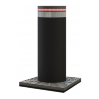
202 RR
Operating instructions and warnings
18
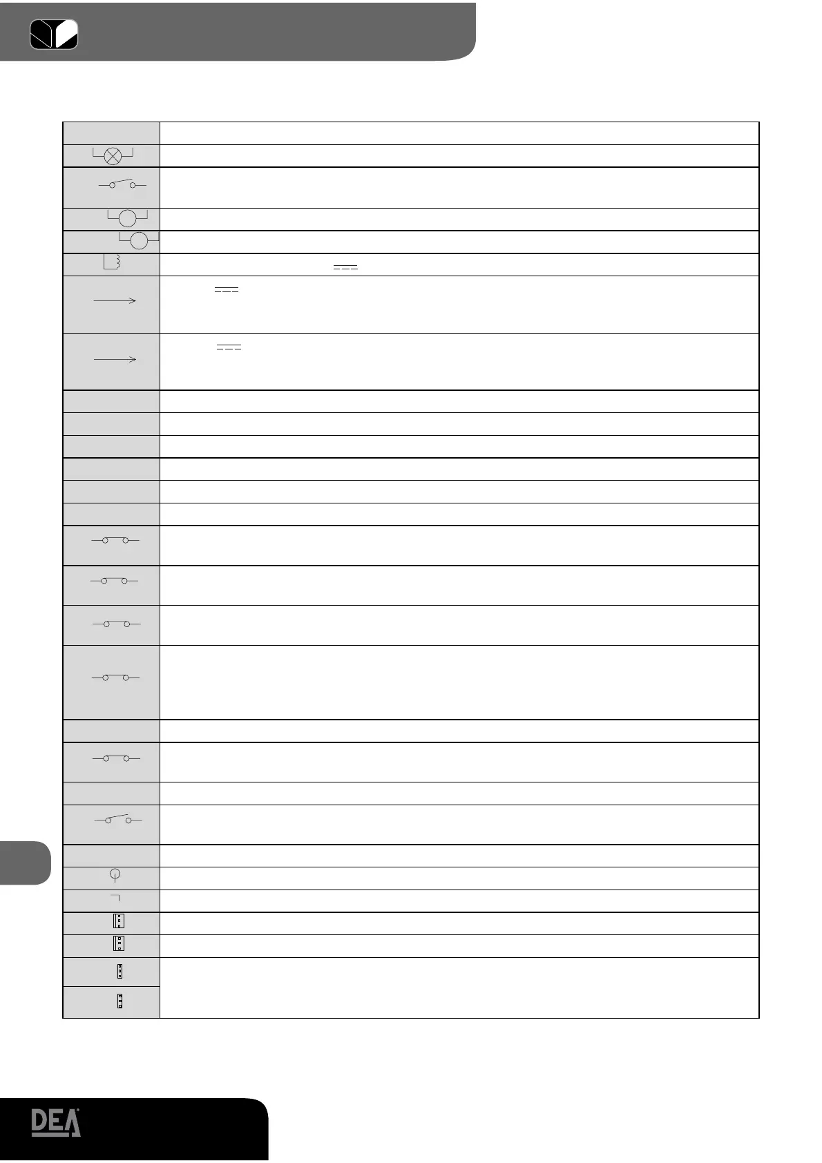
Table 1 Terminal board connection
1-2 230V ~ Power supply input 230 V ~ +/- 10% 50Hz
3-4
LAMP
Flashing light output 230 V ~ max 40W
5-6
LC/SCA
Free contact max. capacity 5A : this contact can be used to control an open gate war-
ning light (P27=0) or a courtesy lamp (P27≠0)
7-8-9
Motor 1 output max 500W (7 opens, 8 common, 9 closes)
10-11-12
Motor 2 output max 500W (10 opens, 11 common, 12 closes)
13-14 ELETTR
Electric lock output 12 V 15VA
15-16
+24VAUX
+24 V power supply output for auxiliary circuits and uncontrolled safety devices To
be used as power supply for any auxiliary devices, photocell receivers (in all cases), and
of safety devices when you don’t want to test these latter before each gate operation.
15-17
+24VSIC
+24 V power supply output for controlled safety devices. To be used as power
supply for photocell transmitters (in all cases) and of safety devices when testing these
latter before each gate operation.
18
not used
19 FCC2
input end of stroke operetor 2 while closing. If unused, short circuit to terminal n°23
20 FCA2
input end of stroke operetor 2 while opening. If unused, short circuit to terminal n°23
21 FCC1
input end of stroke operetor 1 while closing. If unused, short circuit to terminal n°23
22 FCA1
input end of stroke operetor 1 while opening. If unused, short circuit to terminal n°23
23 COM
Common inputs
24
SIC2
N.C. external safety device input of operator 1. In case of activation it reverses the
movement (P18=0) or it stops (P18=1). If unused, short circuit to terminal n°28
25
SIC1
N.C. external safety device input of operator 2. In case of activation it reverses the
movement (P18=0) or it stops (P18=1). If unused, short circuit to terminal n°28
26
FOTO2
N.C. Photocell n. 2 input (external side). In case of activation it reverses the movement
only while closing (P26=0). If unused, short circuit to terminal n°28
27
FOTO1
N.C. Photocell n. 1 input (internal side). In case of activation it stops the movement
and reverses it once the obstacle has been removed. If P26=0 it is not considered, if
P026=1 it stops the movement and reverses it once the obstacle has been removed. If
unused, short circuit to terminal n°28
28 COM
Common inputs
29
STOP
N.C. stop input. If activated, it stops the movement during any operation. If unused,
short circuit to terminal n°32
30 PED
N.O. pedestrian opening button input. If activated, it opens partially the gate
31
START
N.O. open input. If activated, it opens or closes the gate. It can work in “reversal”
mode (P25=0) or “step-by-step” mode (P25=1)
32 COM
Common inputs
33
Aerial signal input
34
Aerial ground input
J9
Connector input for eventual encoder of operator 2
J11
Connector input for eventual encoder of operator 1
J8
Encoder selection Jumper:
•A position = operators with encoder (remind to set P034=0)
•B position = operators without encoder (remind to set P034=1)
J10
M2
M1
A
B
A
B