EN-10
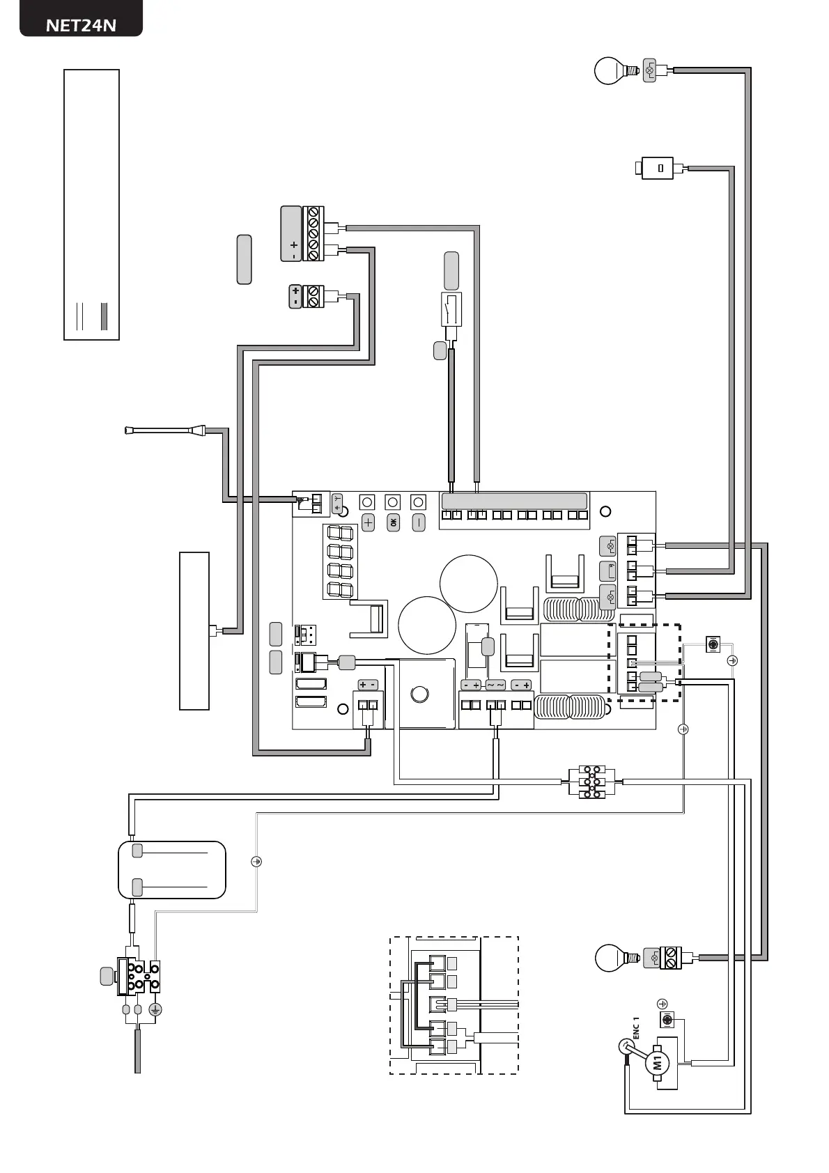
Wiring diagram for TYPE 03 (barrier)
7981110
Diagram for wiring of single barrier
Parallel wiring of M1 output and M2 output
Set P030=001 (1 motor)
!!! All NET24N except version 31 !!!
7981011 12131415
16 17
18
19
20
21
22
23
24
25
26
27
28
29
33
32
2
1
4
3
6
5
ABAB
F2
FLASH
LOCK
WARNING
J5 J9
2 x 0,5 mm
2
INTERNAL WIRING SET BY THE FACTORY
EXTERNAL WIRING SET BY THE INSTALLER
N.O.
RG58
START
TX RX
PHOTO 1
FLASH
OPEN GATE WARNING LIGHT
24V 15W
2 x 0,5 mm
2
2 x 0,5 mm
2
BLUE
RED
2 x 0,5 mm
2
2 x 0,5 mm
2
2 x 0,5 mm
2
COM
N.C.
N.O.
ELECTRO-MAGNET
2 x 1 mm
2
230V
22V
F
N
TRANSFORMER
230V/22V
POWER SUPPLY
230V~ 50Hz ±10%
F1
To terminal 32/33 for normal connection
To terminal 1/2 for controlled safety devices (P071)
ENC
M1
COM
IN_1
COM
IN_2
COM
IN_3
COM
IN_4
COM
IN_5
COM
IN_6