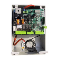
EN-9
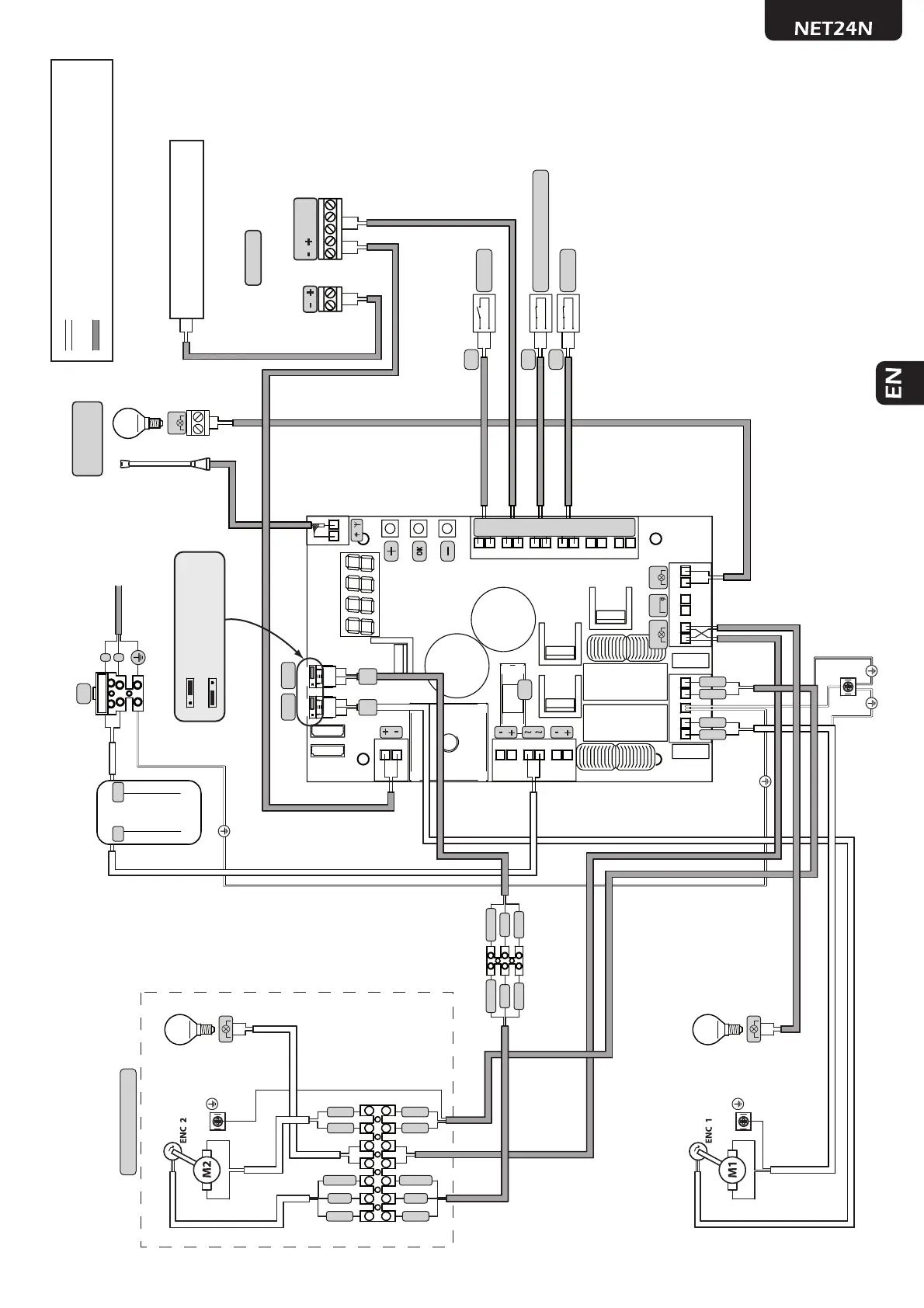
Wiring diagram for TYPE 02 (garage door)
7981011 12131415
16 17
18
19
20
21
22
23
24
25
26
27
28
29
31 30
33
32
2
1
4
3
6
5
ABAB
F2
FLASH
LOCK
WARNING
J5 J9
INTERNAL WIRING SET BY THE FACTORY
EXTERNAL WIRING SET BY THE INSTALLER
N.O.
N.C.
RG58
230V
22V
N.C.
SAFETY (Only if needed)
START
STOP
TX RX
PHOTO 1
LED24AI
max 15W
Mot 2 (Only if present)
TRANSFORMER
230V/22V
POWER SUPPLY
230V~ 50Hz ±10%
COURTESY LIGHT
24V
COURTESY LIGHT
24V
FLASH
F1
2 x 1 mm
2
2 x 0,5 mm
2
2 x 0,5 mm
2
2 x 0,5 mm
2
2 x 0,5 mm
2
2 x 0,5 mm
2
2 x 0,5 mm
2
3 x 1,5 mm
2
3 x 0,22 mm
2
2 x 0,5 mm
2
COM
N.C.
N.O.
2 x 0,5 mm
2
To terminal 32/33 for normal connection
To terminal 1/2 for controlled safety devices (P071)
ENC
M2
ENC
M1
A
A position = operators with encoder
(remind to set P029=0)
B
B position = operators without encoder
(remind to set P029=1)
F
N
BLUE
RED
BLUE
RED
BLUE
RED
BLUE
RED
BROWN
WHITE
GREEN
BROWN
WHITE
GREEN
BROWN
WHITE
GREEN
BROWN
WHITE
GREEN
COM
IN_1
COM
IN_2
COM
IN_3
COM
IN_4
COM
IN_5
COM
IN_6