39
info@debem.it
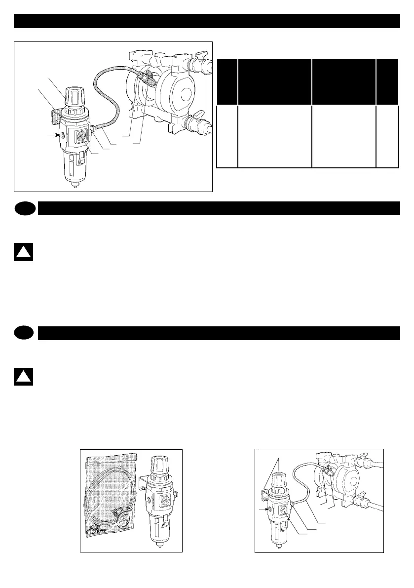
KIT DE RÉGLAGEDE L’AIR
Réglage air
Luftregelung
1
6
5
4
6
3
2
POS.
POS.
DESCRIPTION DESCRIPTION
Q.tà
Q.ty
1
2
3
4
5
6
Filtre réducteur
Bride
Manomètre
5 m. tuyau en Elaston
Robinet
Raccordsi
Reducing lter
Fixing clamp
Ammeter
5-m Elaston hose
Cock
Fittings
Le KIT D’ALIMENTATION DE L’AIR est fourni complet de ltre,
raccords et tuyau de l’air.
ATTENTION: l’alimentation pneumatique de la
pompe doit être effectuée avec de l’air DEPOURVU
D’HUILE, DESSÉCHÉ et préalablement FILTRÉ.
1. Fixer l’équerre de support et groupe ltre à la paroi
2. Monter la soupape de captage sur la pompe.
3. Monter les raccords à dégagement rapide fournis avec la
pompe sur le groupe du ltreet sur la soupape de la pompe.
4. Relier le tuyau de l’air entre le ltreet la pompe sur les rac-
cords prévus en l’introduisant appuyant bien à fond.
5. Relier la ligne d’alimentation de l’air sur le trou du ltre
6. La pression d’alimentation de l’air sur le ltrede réglage doit
être réglée entre le 2 et les 7 bar quand la pompe est en marche.
Le montage du KIT D’ALIMENTATION DEL’AIR est ainsi
terminé.
!
SCHÉMA DE MONTAGE KIT D’ALIMENTATION AIR
kit de reglage
adjustment kit
Réglage air
Air adjustment
1
3
2
4
3
6
F
F
AIR ADJUSTMENT KIT
The AIR SUPPLY KIT comes complete with lter, ttings and
air hose.
WARNING: the pump must be supplied with OIL-
LESS, DRIED and FILTERED AIR.
1. Afx to the wall the supporting bracket and the lter assembly.
2. Assemble the on-off valve onto the pump.
3. Mount the snap couplings on the lter assembly and on the
pump cock.
4. Connect the air hose between the lter and the pump and
insert well on the special ttings.
5. Connect the air supply onto the lter hole.
6. The air supply pressure on the regulator lter must be
between 2 and
7 bar and carried out when the pump is running.
The AIR SUPPLY KIT is nished here.
GB
!
AIR SUPPLY KIT ASSEMBLY LAYOUT
F
GB
GB