Dectron, Inc. March 2012
DSH/DSV/RSH/DBH/RBH Series Dehumidifier Owner’s Manual
Startup Adjust Pool Heating
Data subject to change without notice.
238
DECTRON
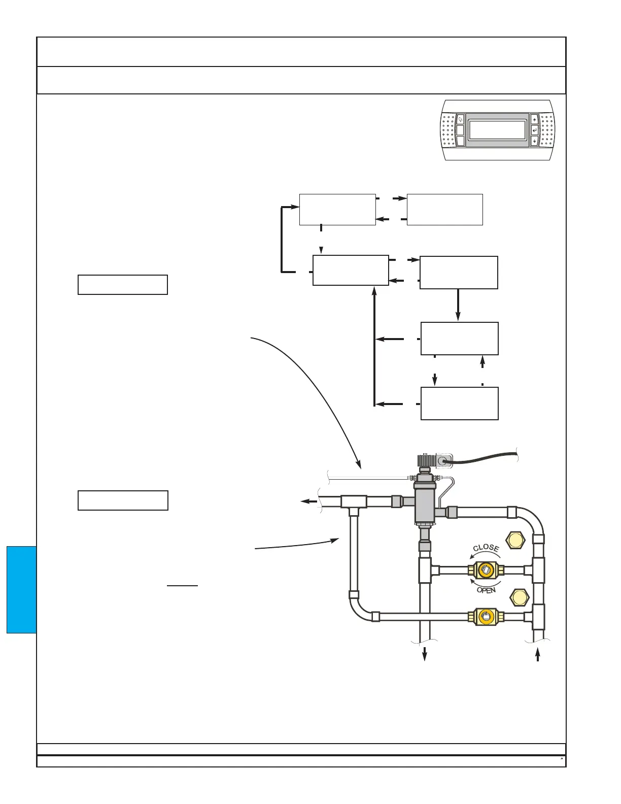
1. Temporarily adjust set points to cause the unit to
operate in dehumidification and pool-heating mode.
Allow 15 minutes of operation before proceeding.
2. Using the interface map at right, note the
temperatures of the inlet pool water and the outlet
pool water.
3. Compute the pool-water temperature
difference when the unit is in pool-heating mode.
Enter the temperature difference in
BOX A.
4. Go to step 5 if the temperature difference is between
10°F (5.5°C) and 20°F (11°C), with the optimum at
12°F (6.7°C). Otherwise, locate the valve assembly for
the correct pool-water heat exchanger.
If Valve B is not present, skip to step 5.
If Valve B is present, call Dectron at 1-800-667-6338
or 1-800-676-2566.
5. Temporarily adjust set points to cause the unit to
stop pool-heating mode and operate in
dehumidification mode only. Allow 10 minutes of
operation before proceeding.
6. Compute the pool-water temperature
difference when the unit is in dehumidification mode
without pool-heating mode. Enter the temperature
difference in
BOX B.
7. The value in BOX B should be greater
than zero and equal to or less than approximately 1/4
of the value in BOX A. If not, locate the valve
assembly for the correct pool-water heat exchanger.
If Valve A is not present, skip to END at bottom of
page. If Valve A is present, slightly
close Valve A to
decrease the temperature difference, or open it to
increase the temperature difference.
8. If Valve A was adjusted in step 7, allow 10 minutes
of operation, then return to step 6.
9. Repeat steps 1 - 8 for any other pools connected to
the unit.
10. Re-install valve caps.
11. Return the set points to their original values, as
specified on the unit nameplate. See Product
Description - Unit Nameplate.
Where units are connected for pool-water heating, the unit must have a constant
pool-water flow rate within ±10% of the recommended values (See T.A.B.). Either a
flowmeter (by others) or a balancing valve (by others) is required to set the pool-water
flow correctly. Check the pool-water flow rate or the Balancing report.
Valve A
Valve B
 Loading...