78
71.06952.02 - EN
INSTALLATION INSTRUCTIONS
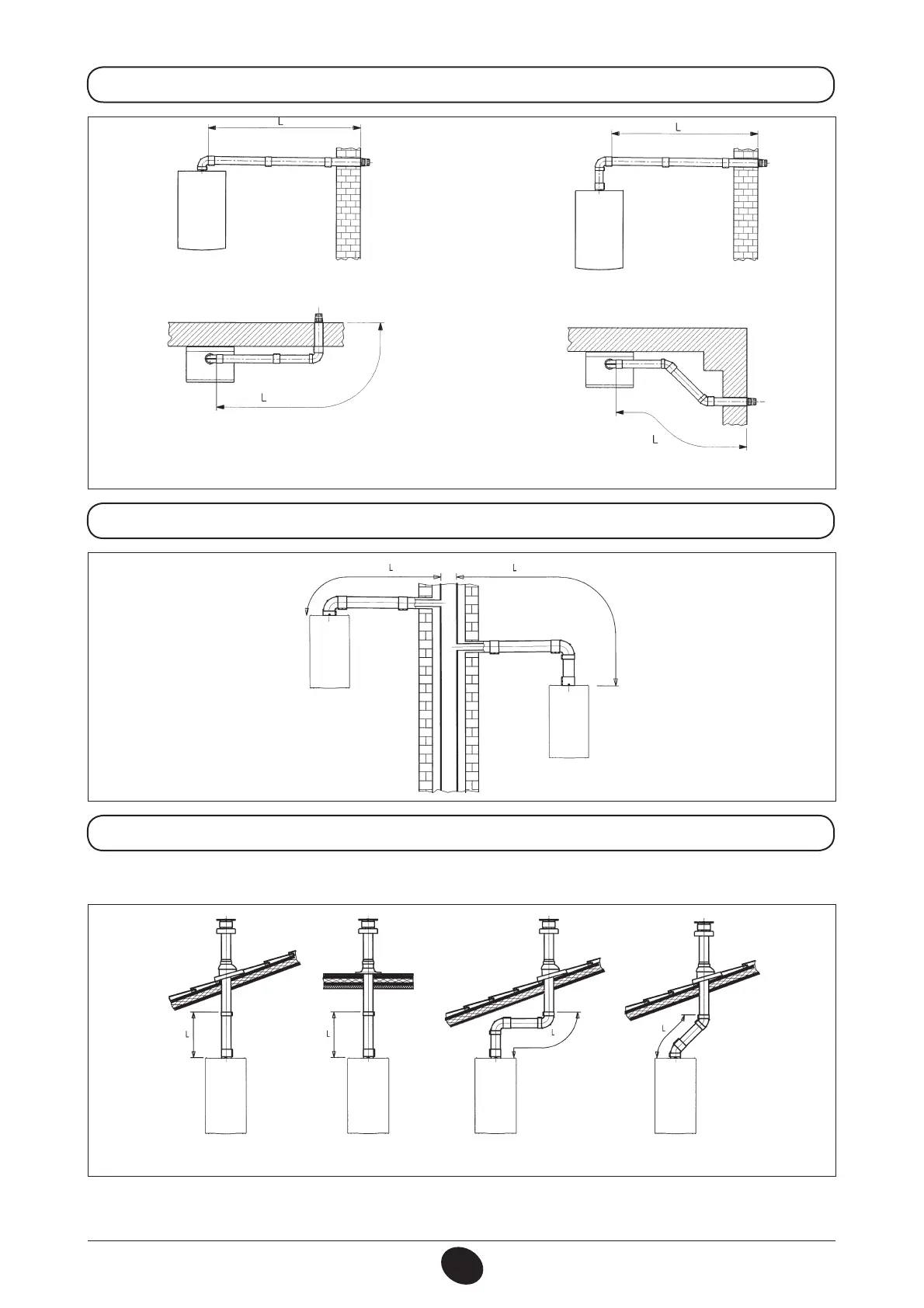
16.1 HORIZONTAL FLUE INSTALLATION EXAMPLES
16.2 LAS FLUE DUCT INSTALLATION EXAMPLES C42 TYPE
16.3 VERTICAL FLUE INSTALLATION EXAMPLES
This type of installation can be carried out on either a at or a pitched roof by tting a ue terminal and a special weathering
surround with sleeve (both available on request).
0503_0908/CG1641 0503_0907/CG1640
0512_2001
For detailed installation instructions, consult the technical data provided with the accessories.
L max = 9 m (Ø 80/125 mm)
L max = 4 m (Ø 60/100 mm)
10 m (Ø 80/125 mm)
L max = 4 m (Ø 60/100 mm)
10 m (Ø 80/125 mm)
L max = 4 m (Ø 60/100 mm)
10 m (Ø 80/125 mm)
L max = 3 m (Ø 60/100 mm)
9 m (Ø 80/125 mm)
L max = 3 m (Ø 60/100 mm)
9 m (Ø 80/125 mm)
L max = 7 m (Ø 80/125 mm)
L max = 8 m (Ø 80/125 mm)
 Loading...