77
71.06952.02 - EN
INSTALLATION INSTRUCTIONS
16. INSTALLING THE FLUE AND AIR DUCTS
Model 24 MI FF - 24 FF
The boiler is easy and exible to install thanks to the ex-
tensive range of available accessories, as described below.
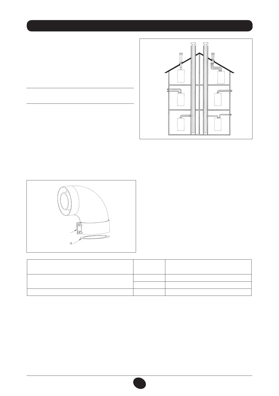
The boiler has been designed for connection to a vertical
or horizontal coaxial ue-air duct. A splitting kit is also
available if separate ducts are required.
Only accessories supplied by the manufacturer must
be used for installation!
WARNING: To optimise operating safety, make sure
the flue ducts are firmly fixed to the wall with suitable
brackets.
Figure 6
0503_0905/CG1638
… COAXIAL FLUE-AIR DUCT (CONCENTRIC)
This type of duct is used to discharge exhaust fumes and draw combustion air both outside the building and if a LAS ue
is tted.
The 90° coaxial curve allows the boiler to be connected to a ue-air duct in any direction as it can be rotated by 360°. It
can also be used as a supplementary curve combined with a coaxial duct or a 45° curve.
If fumes are discharged outside the building, the ue-air duct
must protrude at least 18 mm from the wall to allow an alu-
minium weathering surround to be tted and sealed to avoid
water inltrations.
Make sure there is a minimum upward slope towards the
outside of 1 cm per metre of duct.
r
A 90° curve reduces total duct length by 1 metre.
r
A 45° curve reduces total duct length by 0.5 metres.
The first 90° curve is not considered when calculating the
maximum available length.
Figure 7
0805_2901 / CG_2073
Connector
Diameter coaxial flue-air duct (mm)
Lenght
(m)
Use of DIAPHRAGM on
INLET LINE A (mm)
60/100
0 ÷ 1 Ø 80
1 ÷ 4 NO
80/125 0 ÷ 10 Ø 90
 Loading...