82
71.06952.02 - EN
INSTALLATION INSTRUCTIONS
19. GAS CONVERSION
The authorised Technical Assistance Service can convert this boiler to natural gas (G. 20) or liquid gas (G.31).
Carry out the following operations:
A) replace the nozzles of the main burner and the gas diaphragm (if tted);
B) new max. and min. calibration of the pressure regulator.
A) Replace the burner nozzles
rDBSFGVMMZQVMMUIFNBJOCVSOFSPGGJUTTFBU
rSFQMBDFUIFNBJOCVSOFSOP[[MFTNBLJOHTVSFUPGVMMZUJHIUFOUIFNUPQSFWFOUHBTMFBLT/P[[MFEJBNFUFSTBSFTQFDJàFE
in table 2.
B) Calibrate the pressure regulator
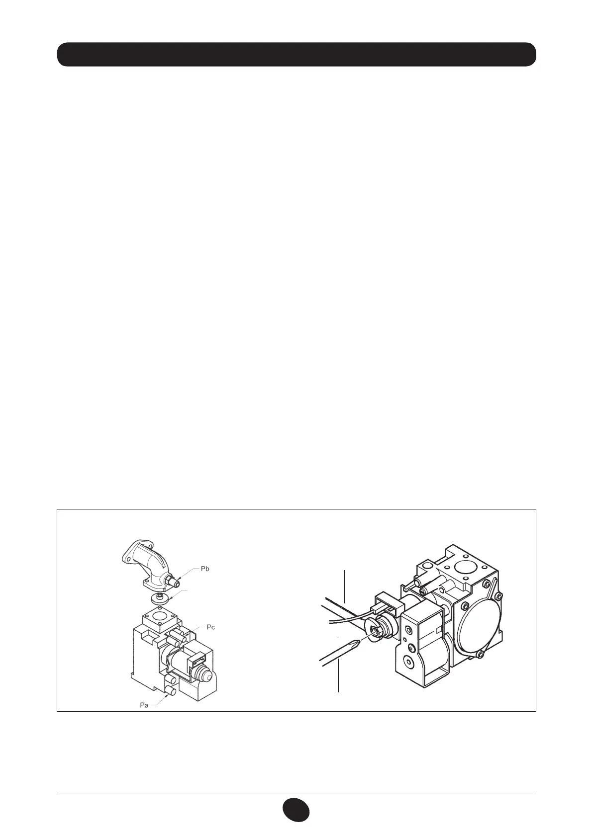
rDPOOFDUUIFQPTJUJWFQSFTTVSFUFTUQPJOUPGBEJGGFSFOUJBMQSFTTVSFHBVHFQPTTJCMZXBUFSPQFSBUFEUPUIFHBTWBMWF
pressure test point (Pb) (Figure 10). Only for models with sealed chambers, connect the negative pressure test point of
the manometer to a “T” tting in order to join the boiler adjustment outlet, the gas valve adjusting outlet (Pc) and the
pressure gauge. (The same measurement can be made by connecting the pressure gauge to the pressure test point
(Pb) after removing the front panel of the sealed chamber);
Measuring burner pressure using methods other than those described could lead to incorrect results as the low pressure
created by the fan in the sealed chamber would not be taken into account.
B1) Adjustment to nominal heat output:
rPQFOUIFHBTUBQBOETXJUDIUIFCPJMFSUPUIF8JOUFSNPEF
rPQFOBIPUXBUFSUBQUIBUDBOQSPWJEFBáPXSBUFPGBUMFBTUMJUSFTBNJOVUFPSNBLFTVSFUIFSFJTNBYJNVNIFBU
demand;
rSFNPWFUIFNPEVMBUPSDPWFS
rBEKVTUUIFUVCFCSBTTTDSFXBVOUJMUIFQSFTTVSFWBMVFTTIPXOJOUBCMFBSFPCUBJOFE
make sure that the dynamic inlet pressure of the boiler, measured at the gas valve pressure test point (Pa) (Figure 10) is
correct (37 mbar for propane or 20 mbar for natural gas).
B2) Adjustment to reduced heat output:
rEJTDPOOFDUUIFNPEVMBUPSQPXFSDBCMFBOEVOTDSFXUIFTDSFXCVOUJMBQSFTTVSFWBMVFDPSSFTQPOEJOHUPSFEVDFEIFBU
output is achieved (see tab. 1);
rSFDPOOFDUUIFDBCMF
rNPVOUUIFNPEVMBUPSDPWFSBOETFBM
B3) Final checks
rBUUBDIUIFBEEJUJPOBMQMBUFTVQQMJFEXJUIUIFUSBOTGPSNFSTQFDJGZJOHUIFUZQFPGHBTBOEUIFDBMJCSBUJPOQFSGPSNFE
Figure 10
gas valve
mod. SIGMA 845
b
a
0605_1502
Figure 11
CG_2273 / 1008_2602
gas diaphragm
ATTENTION
If the natural gas inlet pressure is too low (less than 17 mbar) remove the gas diaphragm installed over the gas valve (g.
10) and set parameter ' on the electronic board (§21).
 Loading...