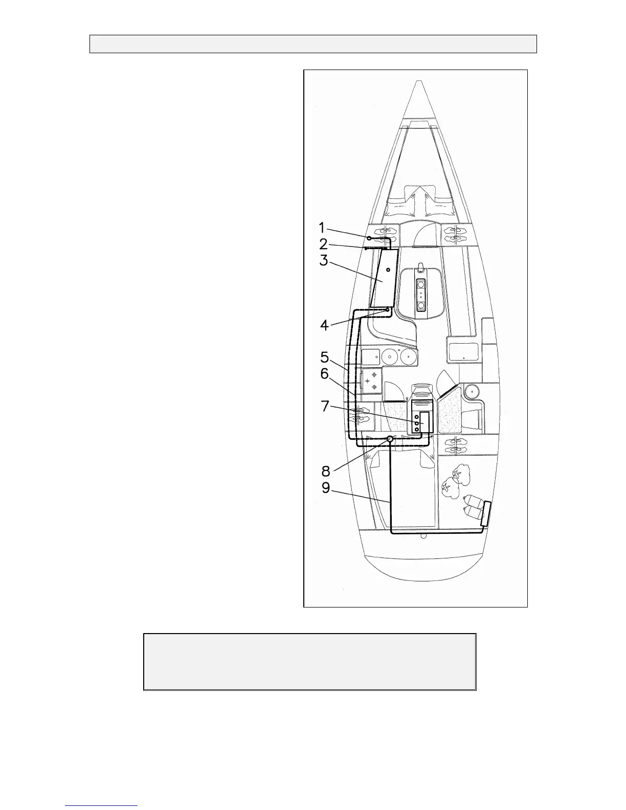
Components
1. Filling cap
2. Ventilation
3. Fuel tank
4. Quick shut off valve
5. Return pipe
6. Feed pipe
7. Inboard diesel engine
8. Filter/Water separator
9. Diesel supply to heating
4.1.5 Engine switch panel
The engine switchboard with a control
lever is installed in the cockpit’s coaming
starboard. All other information can be
found in the extensive information
provided by Volvo.
4.1.6 Engine monitoring
It is especially important to heed the
engine temperature light in calm and tidal
waters. If the water supply is disturbed
engine over-heating may rapidly occur. As
the light does not fall in the field of view
of the skipper an audible warning signal
should reliably prevent such a situation.
See also the instructions in the Volvo
manual.
Figure 11: Fuel lines
NOTE
The single lever circuit is a combination between a circuit and a
throttle. Always allow a few seconds in neutral between gear
changes, to take care of the gear.