The DEIF MIC-2 MKII is a multi-instrument designed for communication and measurement in electrical systems. This quick start guide provides essential information for its installation, operation, and maintenance.
Function Description:
The MIC-2 MKII is a versatile multi-instrument capable of measuring and displaying various electrical parameters, including voltage, current, power (active, reactive, apparent), energy, frequency, and harmonics. It supports different current input types, such as 1/5 A CTs or Flexible Current Transformers, depending on the instrument model. The device features a standard RS485 communication port and can be optionally equipped with Ethernet or Profibus communication modules, allowing for dual communication capabilities. This enables the RS485 serial communication to be used concurrently with either an Ethernet or Profibus connection. The unit also supports I/O modules, which can be configured for digital inputs (DI), digital outputs (DO), relay outputs (RO), analogue inputs (AI), and analogue outputs (AO), expanding its functionality for control, monitoring, and alarming.
Usage Features:
The MIC-2 MKII is designed for ease of use with a clear display and intuitive navigation.
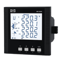
- Display: The display shows metering data, energy data, and a real-time clock. It includes item labels for voltage (U), current (I), active power (P), and other parameters, along with icons for unbalance, THD, TDD, MAX, MIN, and energy (Imp, Total, Net, Exp). The display also indicates the percentage of load current relative to the nominal current, four-quadrant energy, inductive/capacitive load, and the three phases and N. Data units, communication status, energy pulse output, mounted I/O modules, Profibus module, Ethernet module, and a time icon are also displayed.
- Mode Selection: Users can navigate through different modes such as Meter, Max/Min, Demand, Harmonic, Setting, and Digital I/O. Mode selection is performed by pressing specific keys simultaneously, and modes can be changed or entered using dedicated buttons.
- Metering Data Mode (Meter): In this mode, users can view voltage and current, energy, phase angles and unbalance, and power, power factor, and frequency.
- Statistics Data Mode (Max/Min): This mode allows users to switch between Max and Min values and change the view of statistical data.
- Demand Data Mode (Demand): Here, users can change between power and current demand.
- Harmonic Data Mode (Harmonic): This mode provides access to power quality data. Users can switch to harmonic ratio data, display power quality data, switch between voltage and current harmonics, change harmonic order, and switch back to power quality data.
- Settings: The device offers a setting mode for configuring various parameters. Access to this mode requires a four-digit password (default is 0000). Settings are categorized into system parameters ("SYS"), I/O module parameters ("I/O"), Ethernet module parameters ("NET"), and alarm parameters ("ALM").
- Wiring, PT, and CT Settings: Within the "SYS" page, users can configure voltage wiring (S04), current wiring (S05), primary side PT ratio (S06), secondary side PT ratio (S07), primary side CT ratio (S08), and secondary side CT ratio (S09). These settings are adjusted using dedicated keys to increase/decrease digits and move the cursor.
- Communication Settings:
- Modbus: Device address and baud rate can be set on the "SYS" page (S01 and S02). Default settings are device address 1 and baud rate 19200 bps.
- Ethernet (optional): IP Address, Subnet Mask, Gateway, and Primary DNS Server can be configured in the "NET" page. A default password (12345678) is used to access the settings webpage.
- Profibus (optional): Device address can be set from the unit front or via utility software.
- I/O Module Options: The device supports various I/O module combinations (AXM-IO1, AXM-IO2, AXM-IO3) for digital inputs, digital outputs, relay outputs, analogue inputs, and analogue outputs. These modules can be configured for functions like pulse counting, alarm output, energy pulse output, control (latch or pulse), and tracking objects with upper/lower limits. Parameters for I/O modules can be set from the unit front panel or through communication using utility software.
Maintenance Features:
- Warnings and Legal Information: The manual emphasizes the importance of reading installation instructions and safety guidelines to prevent human injury or equipment damage. It states that the unit should not be opened by unauthorized personnel to maintain warranty validity.
- Electrostatic Discharge Awareness: Precautions are advised during installation to protect terminals from static discharges.
- Factory Settings: The unit comes with factory settings based on average values, and users are advised to check and adjust these settings to match their specific engine/generator set before operation.
- Alarming: Up to 16 alarming channels can be selected from 48 available parameters. Alarm channels and conditions are configurable using the utility software, providing a robust monitoring system.
- Utility Software (DEIF View): A free utility software, DEIF View, is available for real-time monitoring and data logging. This software aids in energy saving, power quality analysis, and continuous monitoring of multiple parameters, facilitating maintenance and troubleshooting.
- Documentation: Comprehensive documentation, including the MIC-2 MKII user manual, Ethernet TCP/IP - AXM-Net manual, AXM-Profibus – AXM-PROFI manual, I/O modules - AXM manual, MIC-2 MKII utility software, and GSD file for Profibus, is available for download from the DEIF website, providing detailed information for advanced configuration and maintenance.
- Installation Environment: The unit should be installed in a dry and dust-free environment, away from heat, radiation, and strong electrical interference sources, within a working temperature range of -25°C to 70°C, to ensure optimal performance and longevity.