Do you have a question about the Deif XL96 and is the answer not in the manual?
Details terminal connections and notes for analogue input indicators, including voltage and current inputs.
Specific input for direct connection to rudder potentiometers, including adjustment procedures.
Details terminal connections for dual CANopen indicators, including CAN connections and illumination inputs.
Details terminal connections for sCAN input indicators, including CAN connection and switch/button inputs.
Overview of wiring for BRW-2, including ESD protection, cable dimensions, and PG glands.
Details terminal connections and notes for analogue input on BRW-2, including supply voltage and input types.
Lists terminal connections for CANopen inputs on BRW-2, including CAN lines, supply voltage, and illumination.
Step-by-step instructions for replacing an XL instrument within the BRW-2 housing, including gasket and torque.
Details the commissioning process for analogue indicators, including LED status and out-of-range indication.
Guides on adjusting zero and maximum points for single analogue input indicators using potentiometers.
Details the function of potentiometers A and B for 240° and 360° pointers for gain and zero adjustment.
Covers commissioning for sCAN indicators, including LED status and basic system/indicator settings.
Explains how to enter set-up mode for sCAN indicators using a switch and a 10 k resistor.
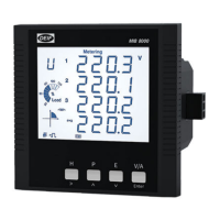
| Accuracy | Class 0.5S (active energy), Class 1 (reactive energy) |
|---|---|
| Input Current | 5A |
| Frequency | 50Hz or 60Hz |
| Digital Output | 2 |
| Frequency Range | 45-65 Hz |
| Display | LCD |
| Communication | RS485 Modbus RTU |
| Protection Class | IP20 |
| Input Voltage Range | 57.7V to 480V (phase to neutral) |