2. XL wiring and installation
2.1 Wiring
2.1.1 Analogue input indicators
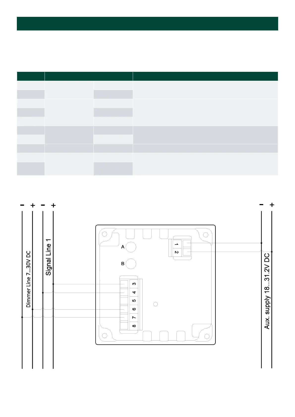
Terminal connections
Pin number
Function Note
1
Supply voltage
0 V
2 24 V
3
Analogue input
Input 1 (Sin)
Input 1 and GND used for single input
On 4 to 20 mA, input 1 is CW and input 2 CCW
Note: GND is mutual for input 1 and input 2
4 GND
5 Input 2 (Cos)
6
Illumination
Illumination +
Dimmer input. Dimmer range 7 to 30 V DC
Consumption max. 30 mA
7 Illumination GND
8 - NC Not connected - can be used freely
A
Analogue
adjustment
Max. adjustment Max. and zero adjustment, sealed by label
On 360 degree versions, A is EM selection and B is zero adjustment
B Zero adjustment
Voltage single input
Installation and commissioning guide 4189350024O EN
Page 6 of 39