Do you have a question about the Deif MIB 8000 and is the answer not in the manual?
Details document content, intended users, and symbols for general and hazard notes.
Covers general safety guidelines, installation safety, electrical connection safety, and electrostatic discharge precautions.
Provides details on technical documentation access, service, support, and training opportunities.
Includes disclaimer regarding document changes, trademark information, and copyright details.
Describes the MIB multi-instrument as a microprocessor-based measuring unit for electrical quantities on 3-phase networks.
Details the MIB's use for measuring electrical quantities in 3-phase systems and its available versions.
Explains the MIB's compatibility with various 3-phase network topologies and input wiring modes for voltage and current.
Provides physical dimensions for the MIB multi-instrument, including front, side, and rear views.
Details RS-485 serial communication and Modbus RTU protocol suitability for SCADA systems.
Lists the electrical measurements performed by the MIB, including voltage, current, power, energy, and THD.
Explains various measured and calculated electrical parameters like reactive power, apparent power, and harmonic distortion.
Describes the sliding window method used for calculating demand of power, reactive power, and current.
Explains the measurement of three-phase voltage and current unbalance factors using sequence vector methods.
Details the MIB's ability to measure and store maximum and minimum values for various system parameters.
Describes how alarms are generated when measured data reaches pre-set limits and alarm times expire.
Explains the use of digital outputs for triggering alarms or indicating over-limit conditions.
Details the use of digital outputs for energy pulse outputs, configurable for active and reactive energy terms.
Illustrates input configurations for 5 Aac/1 Aac and 333mV/100mV (Rogowski coil) current inputs.
Explains how the MIB can be powered by an auxiliary power supply in addition to input configurations.
Details the communication wiring for RS-485 serial communication and Modbus-RTU protocol using terminals A, B, and S.
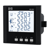
Describes the MIB's backlight display and push-buttons for viewing measured values and configuration during setup.
Explains the MIB's LCD display elements, symbols, and status indicators for various measurements.
States that the parameter setting mode is protected by a four-digit password, with the default being 0000.
Explains that the MIB uses a digital processing platform for sampling and calculating values from input signals.
Details the calculation principles for RMS voltage, current, and power measurements.
Explains how the MIB calculates RMS voltage values and the Modbus equation for data retrieval.
Details the calculation of RMS current values and the Modbus equation for current data retrieval.
Describes the calculation of three-phase and total power values and their display/remote viewing options.
Explains the calculation of reactive power values and the Modbus equation for data retrieval.
Details the calculation of apparent power values and the Modbus equation for data retrieval.
Explains how system frequency is measured and the Modbus equation for frequency data retrieval.
Describes energy measurement (kWh), import/export conventions, and the Modbus equation for energy data retrieval.
Explains reactive energy measurement (kVArh), import/export conventions, and the Modbus equation for data retrieval.
Details apparent energy measurement (kVAh) and the Modbus equation for data retrieval.
Explains the sliding window method for calculating maximum demand and the Modbus equations for demand values.
Details THD measurement for current and voltage, and the Modbus equation for THD data retrieval.
Explains the measurement of voltage and current unbalance factors and the Modbus equations for data retrieval.
Describes the storage of maximum and minimum values for various electrical parameters and data reset options.
Explains the running hour counter function and the Modbus equation for retrieving running hour data.
Provides information on the proper disposal of waste electrical and electronic equipment (WEEE) according to European directives.
| Frequency | 45-65 Hz |
|---|---|
| Digital Output | 2 relay outputs (configurable) |
| Power Consumption | < 5 VA |
| Weight | Approx. 0.5 kg |
| Display | LCD |
| Input Current | 1 A or 5 A |
| Mounting | DIN rail |
| Relative Humidity | Up to 95% non-condensing |
| Protection Class | IP20 |
| Dimensions | 96 x 96 x 83 mm |
| Communication | RS485 Modbus RTU |
| Storage Temperature | -40°C to +70°C |