4. Wiring
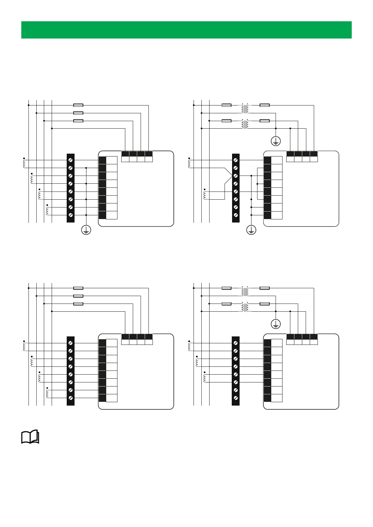
4.1 Input wiring
Input configurations ( 5 Aac / 1 Aac):
LINE
LOAD
Terminal block
L1 L2 L3 N
1A FUSE
MIB
V
N
V3 V2 V1
10 9 8 7
1
I11
2
I12
3
I21
4
I22
5
I31
17 I41
18 I42
6
I32
LINE
LOAD
Terminal block
L1 L2 L3
V
N
V3 V2 V1
10 9 8 7
1
I11
2
I12
3
I21
4
I22
5
I31
17 I41
18 I42
6
I32
1A FUSE
MIB
Input configurations 333 mV / 100 mV (Rogowski coil) / 200 mA / 6.68 mA:
LINE
LOAD
Terminal block
L1 L2 L3 N
1A FUSE
V
N
V3 V2 V1
10 9 8 7
1
I11
2
I12
3
I21
4
I22
5
I31
17 I41
18 I42
6
I32
MIB
LINE
LOAD
Terminal block
L1 L2 L3
1A FUSE
V
N
V3 V2 V1
10 9 8 7
1
I11
2
I12
3
I21
4
I22
5
I31
17 I41
18 I42
6
I32
MIB
More information
See the Installation instructions for more information about installation, panel fitting, and connections.
4.2 Auxiliary power supply wiring
The MIB is typically powered by the input configurations, but can also be powered by an auxiliary power supply.
DESIGNER'S HANDBOOK 4189320063D EN Page 12 of 23