6. Modbus
6.1 How it works
The MIB is based on a digital processing platform. All current and voltage input signals are digitally sampled and all values are
calculated from these sampled signals. The MIB can also measure total harmonic distortion of voltage and current.
6.2 Measuring principles
6.2.1 Voltage (U)
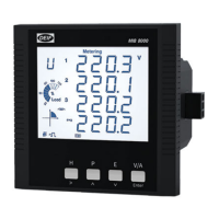
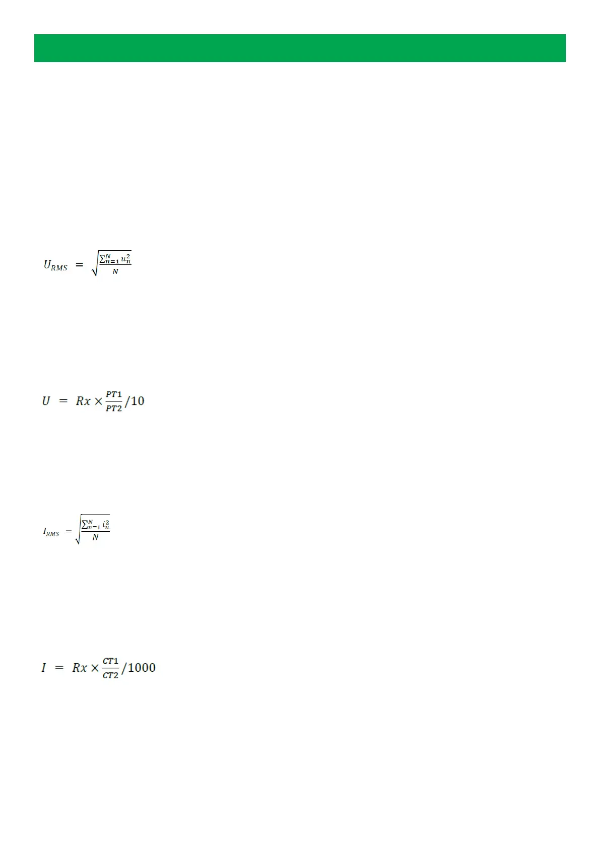
The MIB calculates the true RMS value of the 3 phase-neutral voltages (V1, V2, V3) and the 3 phase-phase voltages (V12, V23,
V32) using this equation:
where N = number of sampled values/period, and u
n
= sampled value. The MIB uses N = 64 for the calculations.
You can see all voltage values on the display. You can also view the values remotely using RS485 communication and MIBLink, the
utility software for MIB.
If you use Modbus to collect the voltage data you need to use this equation to calculate the values:
where Rx = register value, and PT1 and PT2 = voltage transformer data.
6.2.2 Current (I)
The MIB calculates the true RMS value of the three phase currents with this equation:
where N = number of sampled values/period and i
n
= sampled value. The MIB uses N = 64 for the calculations.
You can see the current values on the display. You can also view the values remotely using RS485 communication and MIBLink, the
MIB utility software.
If you use Modbus to collect the current data, you need to use this equation to calculate the values:
where Rx = register value, and CT1 and CT2 = current transformer data.
6.2.3 Power (P)
The MIB calculates the three-phase power and the total power of the system. You can see all the power values on the display. You
can also view the values remotely using RS485 communication and MIBLink, the MIB utility software.
DESIGNER'S HANDBOOK 4189320063D EN Page 17 of 23