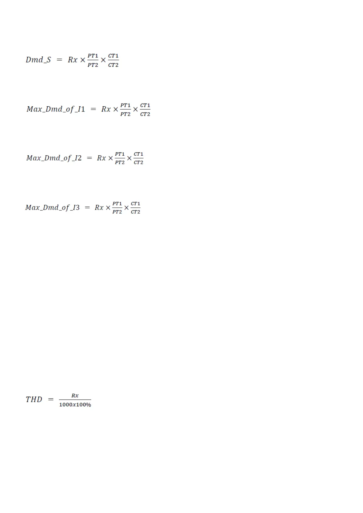
where Rx = register value, CT1 and CT2 = current transformer data, and PT1 and PT2 = voltage transformer data.
Apparent power (S)
where Rx = register value, CT1 and CT2 = current transformer data, and PT1 and PT2 = voltage transformer data.
Current, I1
where Rx = register value, CT1 and CT2 = current transformer data, and PT1 and PT2 = voltage transformer data.
Current, I2
where Rx = register value, CT1 and CT2 = current transformer data, and PT1 and PT2 = voltage transformer data.
Current, I3
where Rx = register value, CT1 and CT2 = current transformer data, and PT1 and PT2 = voltage transformer data.
6.2.11 Total harmonic distortion (THD)
The MIB calculates the total harmonic distortion (THD) for these values:
• The three-phase current
• The average current
• The three phase-neutral voltages*
• The average phase-neutral voltage*
NOTE
* If the voltage input is 2LL, the MIB calculates the TDH for the three phase-phase voltages.
The THD is expressed as a percentage of harmonics due to the fundamental frequency. The MIB uses a true RMS measurement
technique to calculate the values with harmonics present up to 31st harmonics.
You can see the THD values on the display. You can also view the values remotely using RS485 communication and MIBLink, the
MIB utility software.
If you use Modbus to collect the THD data, you need to use this equation to calculate the THD values:
where Rx = register value.
6.2.12 Three-phase unbalance factor
The MIB can measure the three-phase voltage unbalance factor and the three-phase current unbalance factor. The factor is
expressed in percentage, and is calculated using these equations:
DESIGNER'S HANDBOOK 4189320063D EN Page 20 of 23