Mounting
According to the DIN standard.
Mount the indicator from the front of the panel, through the hole, and use the fixing
clamps to fasten the indicator from the rear side.
Type/size Panel cutout
(mm)
Tolerance
(mm)
IP52 fixing
clamps
IP66 fixing
clamps
XL72 68.5 × 68.5 -0.0/+0.7 2 4
XL96 92.5 × 92.5 -0.0/+0.8 2 4
XL144 138.5 × 138.5 -0.0/+1.0 4 8
XL192 186.5 × 186.5 -0.0/+1.1 4 8
Do not remove the front window protection until the installation has been approved by the
class surveyor.
IP66 option
Additional clamps and a gasket are supplied for IP66 mounting. Carefully mount the
gasket into the groove of the frame; the flat side goes into the groove and the rounded
side faces outwards. Make sure that the gasket is evenly mounted and not capsized.
Warranty label
If this label is removed or broken, the warranty will be lost. Do not open the product! It is
likely to be damaged permanently.
Power-up the first time
When the indicator is without power, the pointer position is random.
The indicator is equipped with an amber LED lamp in the lower corner of the scale area.
After power-up, the LED will flash once or twice and is then turned off.
When power is applied, the pointer will be out of control for a few seconds. This is normal
operation.
Analogue version:
There is a “maximum” and a “zero” adjustment on the rear side of the indicator. These
are normally sealed at delivery.
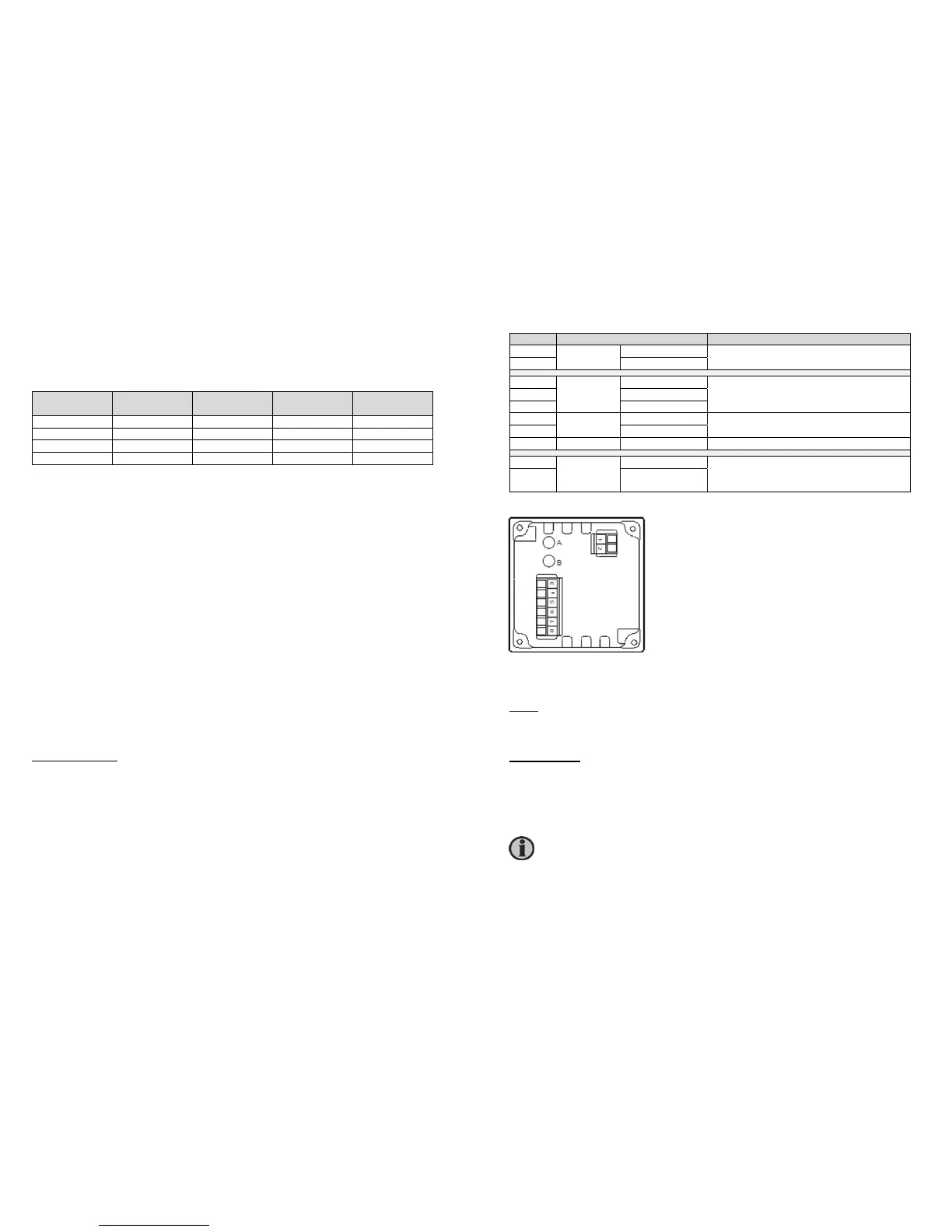
Wiring of analogue version
Pin no. Function Note
1
Supply
voltage
0 V
Consumption max. 150 mA
2 24 V
3
Analogue
input
Input 1 (Sin)
Input 1 and GND used for single input. On
4 to 20 mA, input 1 is CW and input 2 CCW
Note: GND is mutual for inputs 1 and 2
4 GND
5 Input 2 (Cos)
6
Illumination
Illumination + Dimmer input. Dimmer range 7 to 30 V
dc
Consumption max. 30 mA
7 Illumination GND
8 - NC Not connected – can be used freely
A
Analogue
adjustment
Max. adjustment Max. and zero adjustment, sealed by label.
On 360 degree versions, A is EM selection
and B is zero adjustment
B Zero adjustment
sCAN version
Setup:
Special means for minimum, zero and maximum setting of the pointer are provided. The
pointer rotation direction can also be changed.
Dimmer wiring:
Remember that even if CAN dimming is used, there must be a supply connection to the
dimmer circuit on pins 10-11. This is due to the fact that the dimmer circuit is galvanically
separated from the built-in power supply.
A direct connection between terminals 1-10 and 2-11 will enable the illumination.
The CANbus must be terminated with a 120 Ohm resistor at both ends of
the line.