Service Manual
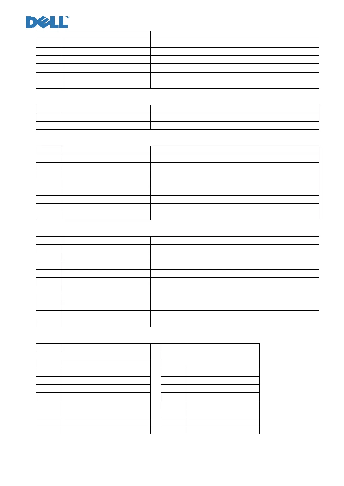
24 GND_LVDS LVDS Ground
25 RXO2+ LVDS signal of even channel 2(+)
26 RXO2- LVDS signal of even channel 2(-)
27 RXO1+ LVDS signal of even channel 1(+)
28 RXO1- LVDS signal of even channel 1(-)
29 RXO0+ LVDS signal of odd channel 0(+)
30 RXO0- LVDS signal of odd channel 0(-)
11.2 CN1, CN2, CN3, CN4 (Connect to Panel Backlight, SM02B-BHSS-1-TB or compatible connector)
Pin Symbol Description
1 HV High voltage for lamp
2 LV Low voltage for lamp
11.3 CN401 (Connect IF to keypad S8B-PH-K or compatible connector)
Pin Symbol Description
1 Audio Detect Sound bar detect pin
2 LED Amber LED Green on/off control
3 LED Green LED amber on/off control
4 UP keypad “+” control
5 DOWN Keypad “-” control
6 MENU Keypad “MENU” control
7 Select Input signal Select
8 GND GND
11.4 CN601 (Connect Power/Inverter with IF board)
Pin Symbol Description
1 GND GND
2 GND GND
3 GND GND
4 Audio Detect Sound bar detect
5 SUB_DC_ON/OFF +5V on/off control
6 +5V DC_+5V
7 +5V DC_+5V
8 +5V DC_+5V
9 Brightness Brightness control
10 CCFL_ON/OFF CCFL ON/OFF control
11.5 CN901 (Connect I/F with transfer USB Board) & CN102
Pin Symbol Pin Symbol
1 GND 1 GND
2 PWR3 2 PWR4
3 DD3M 3 DD4M
4 DD3P 4 DD4P
5 GND 5 GND
6 GND 6 GND
7 DD4P 7 DD3P
8 DD4M 8 DD3M
9 PWR4 9 PWR3
10 GND
10 GND