Service Manual
Chapter 3- CIRCUIT THEORY
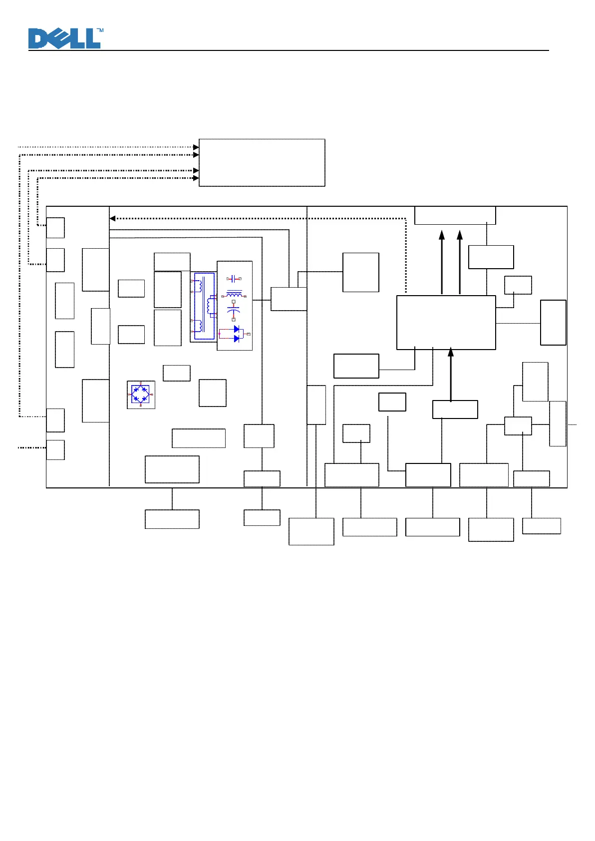
1. Block Diagram
There are 4 pieces PCBA in monitor, one is power/inverter board which is single layer board, one is
Interface board with USB HUB (1up/2down) which is two layers board, one is keypad board, one is USB
transfer board located on side of monitor.
Backlight ON-OFF/Brightness CTRL
+5V
+16V
5V
+16V
T850
R. G. B. H. V
D850
DDC_CLK
DDC_DATA
for Panel
U401
Gm5621-LF
XTAL
14.318MHz
Serial flash
5V-3.3V
3.3V-1.8V
DVI
Board
M170EG01 (AUO)
LM170E01-TLB3/B4 (LPL)
CN3
CN1
OZ9936G
AP9971G
AC Socket
817B
.
.
.
2
1
4
6
9
8
AP2761
SNUBBER
SG6841
1
2
3
-+
1
2
4
Input
pump
Current
sense
CN2
CN4
AP9971G
16V-12V
CN853
16V-5V
CN401
P001, P002
Input
Device
XTAL
24MHz