I/O Ports and Connectors B-3
address and allowable IRQ settings. It should also pro-
vide instructions for readdressing the port and changing
the IRQ setting, if necessary.
The built-in parallel port has autoconfiguration capability
through the System Setup program. That is, if you set the
parallel port to its automatic configuration and add an
expansion card containing a port configured as LPT1
(IRQ7, I/O address 378h), the system automatically
remaps the built-in parallel port to its secondary address
(IRQ5, I/O address 278h). If the secondary port address is
already being used, the built-in parallel port is turned off.
For more information, see “Parallel Port” in Chapter 4.
For general information on how your operating system
handles serial and parallel ports as well as for more
detailed command procedures, see your operating system
documentation.
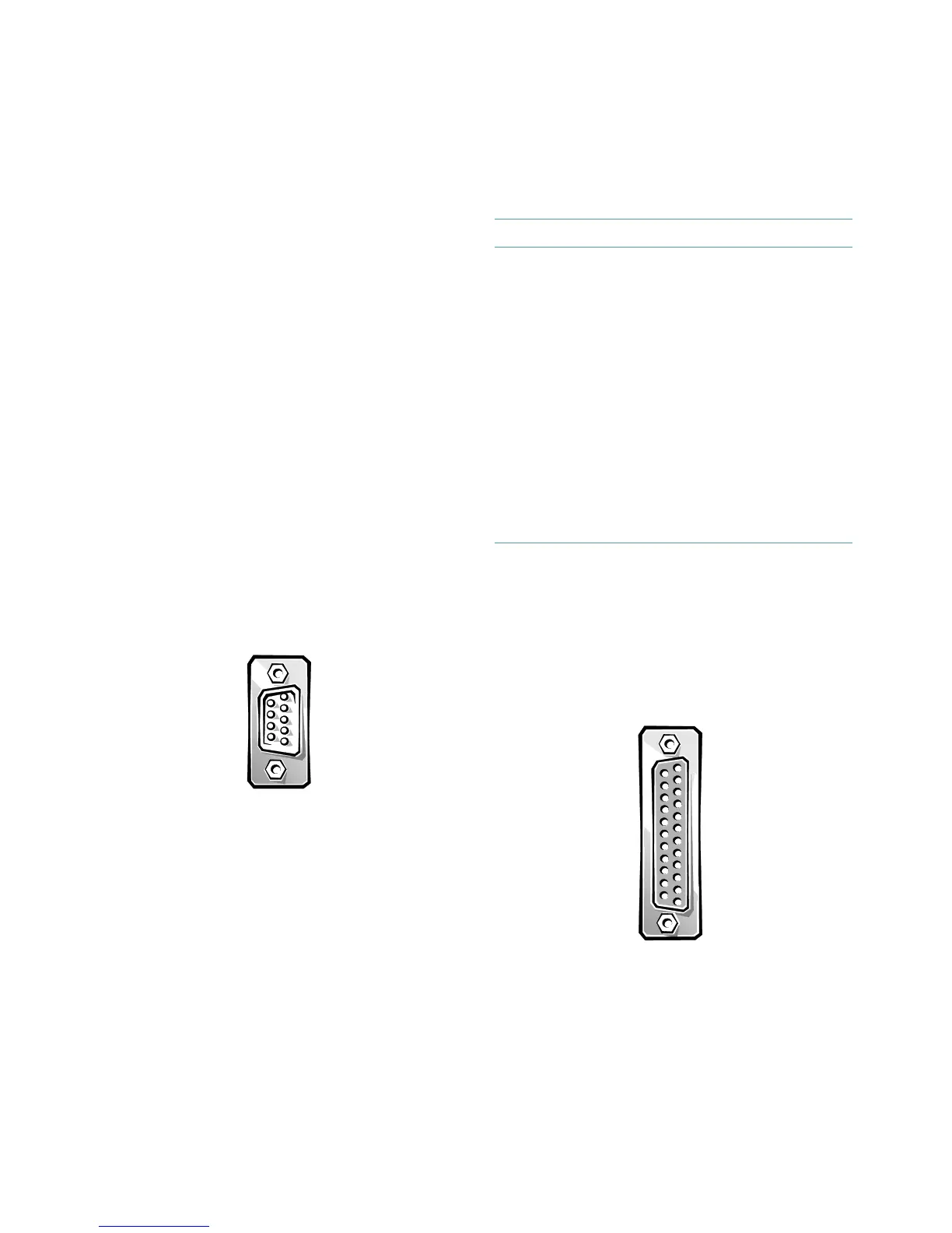
Serial Port Connectors
If you reconfigure your hardware, you may need pin
number and signal information for the serial port connec-
tors. Figure B-2 illustrates the pin numbers for the serial
port connectors, and Table B-1 lists and defines the pin
assignments and interface signals for the serial port
connectors.
Figure B-2. Pin Numbers for the Serial Port
Connectors
Parallel Port Connector
If you reconfigure your hardware, you may need pin
number and signal information for the parallel port con-
nector. Figure B-3 illustrates the pin numbers for the
parallel port connector, and Table B-2 lists and defines
the pin assignments and interface signals for the parallel
port connector.
Figure B-3. Pin Numbers for the Parallel Port
Connector
1 — 5
6 — 9
Table B-1. Pin Assignments for the Serial Port
Connectors
Pin Signal I/O Definition
1 DCD I Data carrier detect
2 SIN I Serial input
3 SOUT O Serial output
4 DTR O Data terminal ready
5 GND N/A Signal ground
6 DSR I Data set ready
7 RTS O Request to send
8 CTS I Clear to send
9 RI I Ring indicator
Shell N/A N/A Chassis ground
1 — 13
14 — 25