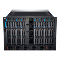
15. Slide the 3 piece housing components in place, and then using the 1.5 mm hex wrench tighten the screws on the RTN side.
Figure 4. Attaching each -48V and RTN housing, tightening the screws on the RTN side
16. Repeat the same process for each PSU.
17. Connect the other end of the power cable to the DC power source by using appropriate crimping of ring terminal or lugs and
heat-shrink tubing.
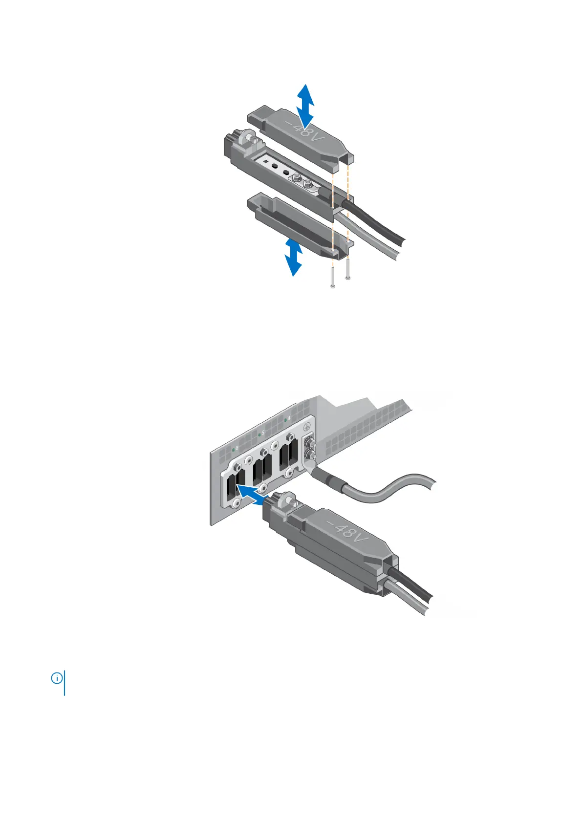
18. To connect the –48V DC power cable, plug each –48V DC power cable/connector assembly into each receptacle at the rear
of the chassis.
Figure 5. Connect the –48V DC power cable
19. Tighten the threaded screw on the -48V side.
NOTE:
The power cable receptacles 1 to 3 are located on the right side, and power cable plugs 4 to 6 are located on the
left of the rear view of the chassis. These correspond to the -48V DC PSUs installed from the front of the chassis.
8 Assembling the -48V DC power input connector and cables
 Loading...