14. Replace the screw (M2x3) that secures the display-cable bracket to the system board.
15. Adhere the tape that secures the display-cable bracket to the system board.
Next steps
1. Install the base cover.
2. Exit Service Mode.
3. Follow the procedure in After working inside your computer.
I/O board
Removing the I/O board
Prerequisites
1. Follow the procedure in Before working inside your computer.
2. Enter Service Mode.
3. Remove the base cover.
About this task
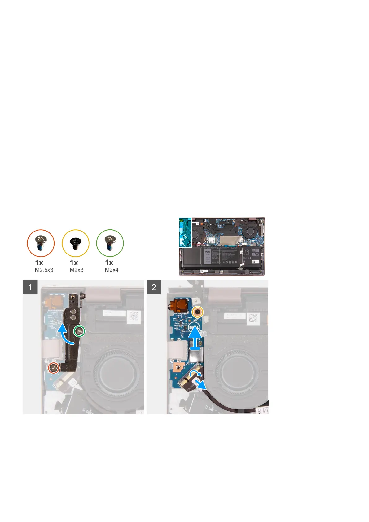
The following image(s) indicate the location of the I/O board and provides a visual representation of the removal procedure.
Steps
1. Lift the I/O-board cable-connector latch and disconnect the I/O-board cable from the I/O board.
2. Remove the screw (M2x3) that secures the left-display hinge to the palm-rest and keyboard assembly.
3. Remove the screw (M2x4) that secures the left-display hinge to the palm-rest and keyboard assembly.
4. Pry open the left-display hinge.
5. Remove the screw (M2x3) that secures the I/O board to the palm-rest and keyboard assembly.
40
Removing and installing components
 Loading...