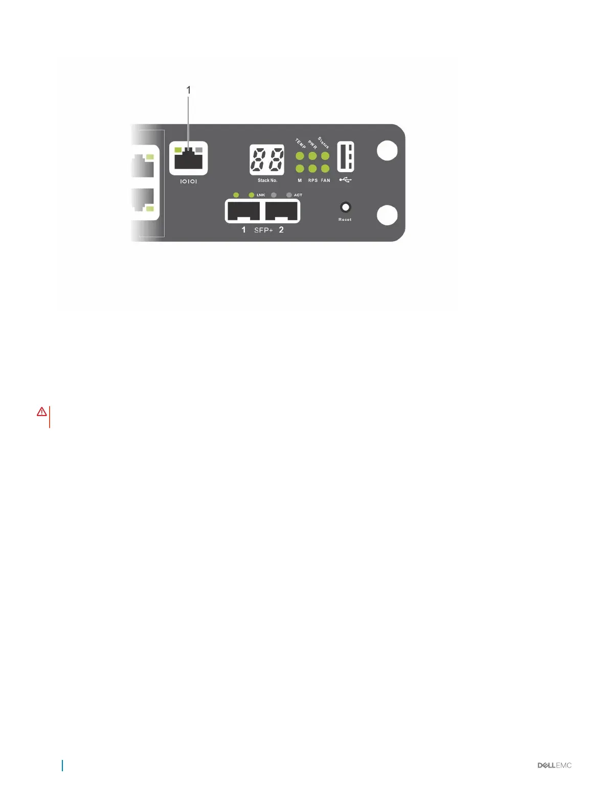
Figure 9. N2024P Console Port Location
1 Console port
Connecting an N20xx Switch to a Power Source
WARNING
: Read the safety information in the
Safety and Regulatory Information
manual and the safety information for other
switches that connect to or support the switch.
All N20xx models have one internal power supply. The power receptacles are on the PSU-side.
AC and DC Power Connection
1 Make sure that the switch console port is connected to a VT100 terminal or VT100 terminal emulator using the RJ-45 to DB-9 female
cable.
2 Using a 5-foot (1.5–meter) standard power cable with safety ground connected, connect the power cable to the AC main receptacle
on the PSU-side.
3 Connect the power cable to a grounded AC outlet.
4 If you are using a redundant or external DC power supply, such as the Dell Networking RPS720 or Dell Networking MPS1000, connect
the DC power cable to the DC receptacle on the PSU-side. The redundant power supply feed is located in the middle and is labeled
RPS.
16
Starting and Configuring the N20xx Switch
 Loading...