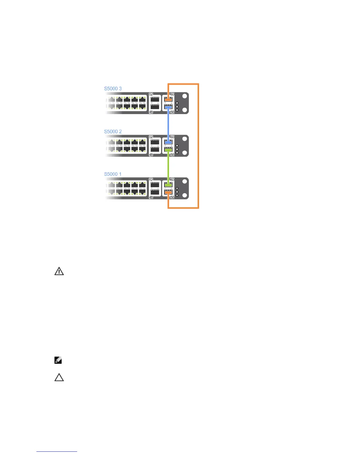
3. Insert the second cable into stack port 60 of chassis 2 (center) and port 56 of chassis 3 (top).
4. Use the third cable to connect the top and bottom units by inserting one end of the cable into stack port 56 on
chassis 1 (bottom) and the other end of the cable into stack port 60 on chassis 3 (top).
Figure 26. Three S5000s Connected in a Ring
Supplying Power and Powering Up the System
Supply power to the S5000 system after the chassis is mounted in a rack or cabinet.
WARNING: Installing and swapping of Fibre Channel or Ethernet modules must be done BEFORE power up. If you
need to replace a module, power down the system before you replace it. If you replace a module when the system
is powered up, the system does not recognize the module. Online insertion of modules can result in a catastrophic
failure.
Dell Networking recommends reinspecting your system prior to powering up. Verify that:
• The equipment is properly secured to the rack.
• The equipment rack is properly mounted and grounded.
• The ambient temperature around the unit (which may be higher than the room temperature) is within the limits
specified for the S5000.
• There is sufficient airflow around the chassis.
• The input circuits are correctly sized for the loads and that you use sufficient overcurrent protection devices.
NOTE: For powering up an AC PSU, an AC power cable is included in the shipping container. You must order all
other power cables separately.
CAUTION: ESD damage can occur if the components are mishandled. Always wear an ESD-preventive wrist or
heel ground strap when handling the S5000 and its components.
41