Back to Contents Page
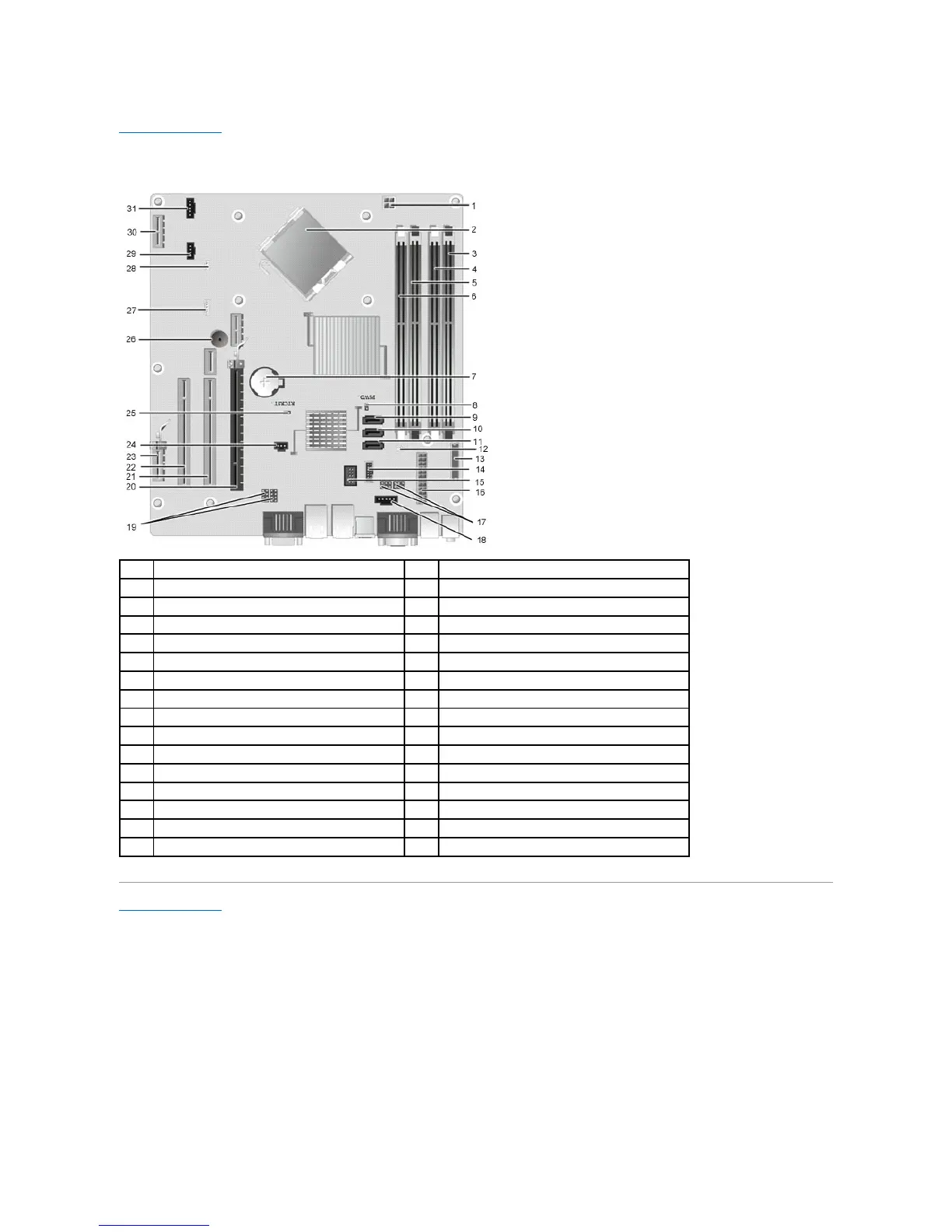
System Board Layout
Dell™OptiPlex™XEDesktopServiceManual—Desktop
Back to Contents Page
processor power connector (12VPOWER)
memory module connectors (DIMM_4)
memory connector (DIMM_2)
memory module connectors (DIMM_3)
memory connector (DIMM_1)
SATA drive connectors (SATA0)
SATA drive connectors (SATA1)
SATA drive connectors (SATA2)
thermal sensor connector (rear)
front-panel connector (FRONTPANEL)
external power USB connector
serial port jumper (J3 & J4)
power connector (24V POWER)
serial port jumper (J1 & J2)
PCI Express x16 slot (SLOT1)
PCI Express x1 slot (SLOT4)
chassis intrusion switch connector (INTRUDER)
RTC reset jumper (RTCRST)
thermal Sensor connector (front)
PCI Express slot x1 (Slot6)