3. Remove the base cover.
4. Remove the 4G WWAN card or 5G WWAN card, as applicable.
5. Remove the WLAN card.
6. Remove the memory modules.
7. Remove the M.2 2230 or M.2 2280 solid-state drive from Slot 1, as applicable.
8. Remove the M.2 2230 solid-state drive from Slot 2, if applicable.
9. Remove the battery.
10. Remove the assembly-inner frame.
11. Remove the system board.
NOTE: The system board can be removed with the heat sink attached in order to simplify the procedure and preserve
the thermal bond between the system board and heat sink.
12. Remove the display assembly.
13. Remove the smart-card reader, if applicable.
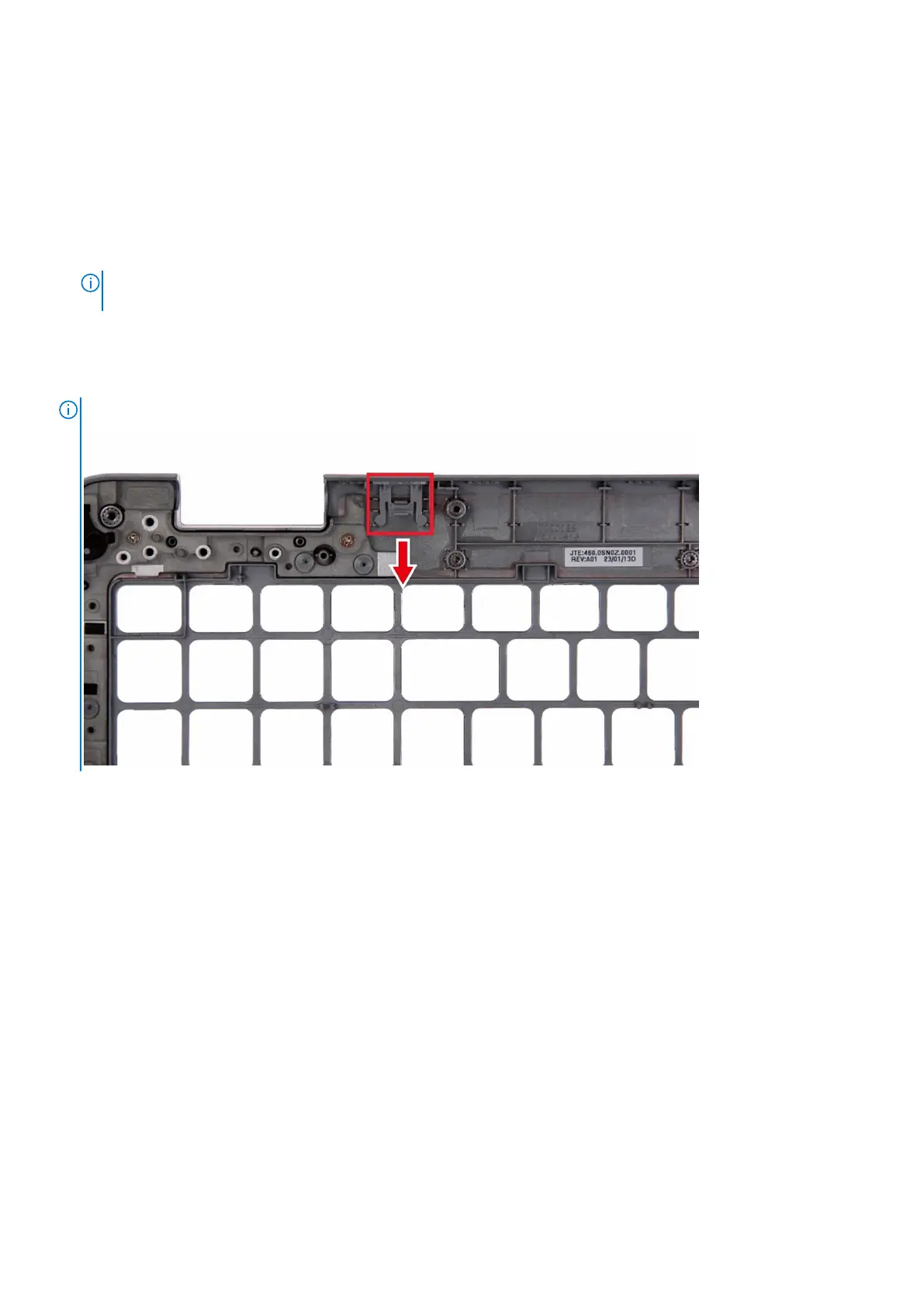
About this task
NOTE: When replacing the palmrest assembly, transfer the dummy SIM filler to the new palmrest assembly.
The following images indicate the location of the palm-rest assembly and provide a visual representation of the removal
procedure.
Removing and installing Field Replaceable Units (FRUs)
125