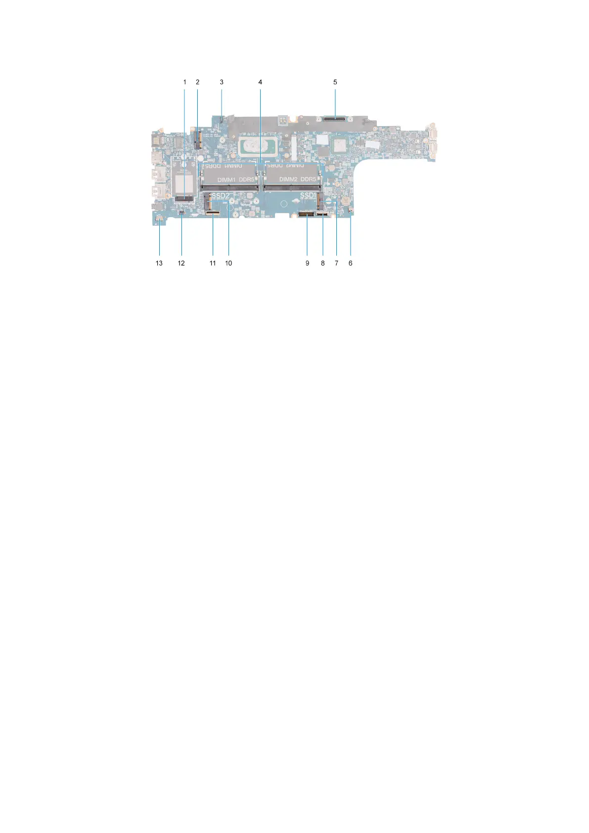
1. WWAN card connector 2. WLAN card connector
3. eDP cable connector 4. Memory modules
5. Display cable connector 6. System fan connector
7. Solid-state drive Slot 1 8. Touchpad cable connector
9. Battery cable connector 10. Solid-state drive Slot 2
11. USH-cable connector 12. Coin-cell battery cable connector
13. Speaker cable connector
The following images indicate the location of the system board and provide a visual representation of the installation procedure.
Removing and installing Field Replaceable Units (FRUs)
87