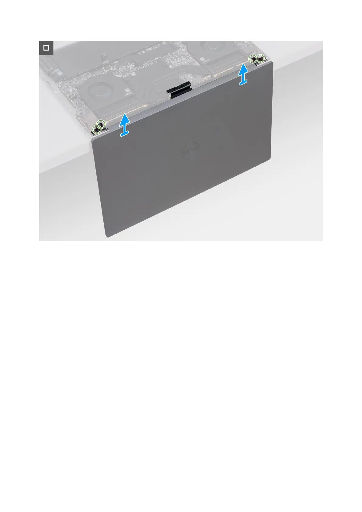
Figure 39. Removing the display assembly
Steps
1. Remove the two screws (M1.4x1.3) that secure the display-cable cover to the display-cable connector bracket.
2. Remove the two screws (M2x3) that secure the display-cable connector bracket to the system board.
3. Lift the bracket off the system board.
4. Disconnect the two display cables from the connectors (CAM1) on the system board.
5. Open the palm rest and keyboard assembly at an angle and remove the display assembly.
6. Remove the two screws (M2.5x6) that secure the left-display hinge to the palm rest and keyboard assembly and open the
left hinge.
7. Remove the two screws (M2.5x6) that secure the right-display hinge to the palm rest and keyboard assembly and open the
right hinge.
8. After performing all the above steps, you are left with the display assembly.
60
Removing and installing Field Replaceable Units (FRUs)