6. Remove the heat sink.
7. Remove the Type-C brackets.
About this task
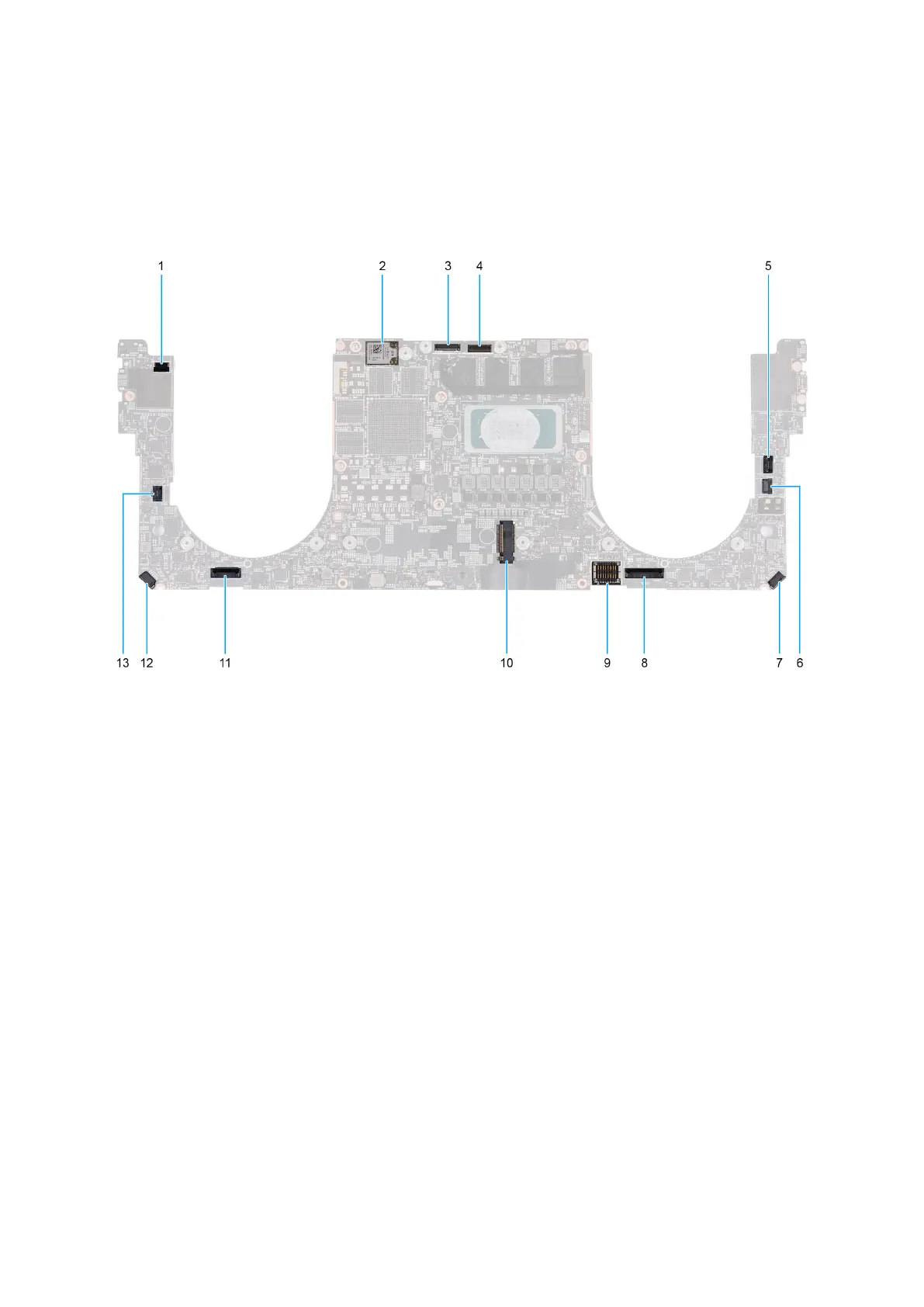
The following image indicates the connectors on your system board.
Figure 45. System-board connectors
1. Power-button and fingerprint reader cable connector (FP1)
2. Antenna-cable connectors (MAIN 2 and AUX 1) on wireless module
3. Camera-cable connector (CAM1)
4. Display assembly cable connector (LCD1)
5. Capacitive touch-panel cable connector (TF1)
6. CPU fan cable connector (FAN2)
7. Speaker (L) cable connector (SPKL1)
8. Touchpad-cable connector (TPAD1)
9. Battery-cable connector (BATT)
10. Solid-state drive slot (SSD1)
11. Keyboard-cable connector (CN6501)
12. Speaker (R) cable connector (SPKR1)
13. GPU fan cable connector (FAN1)
The following image(s) indicate the location of the system board and provides a visual representation of the removal procedure.
66
Removing and installing Field Replaceable Units (FRUs)