4. Display assembly cable connector (LCD1)
5. Capacitive touch-panel cable connector (TF1)
6. CPU fan cable connector (FAN2)
7. Speaker (L) cable-connector (SPKL1)
8. Touchpad-cable connector (TPAD1)
9. Battery-cable connector (BATT)
10. Solid-state drive slot (SSD1)
11. Keyboard-cable connector (CN6501)
12. Speaker (R) cable connector (SPKR1)
13. GPU fan cable connector (FAN1)
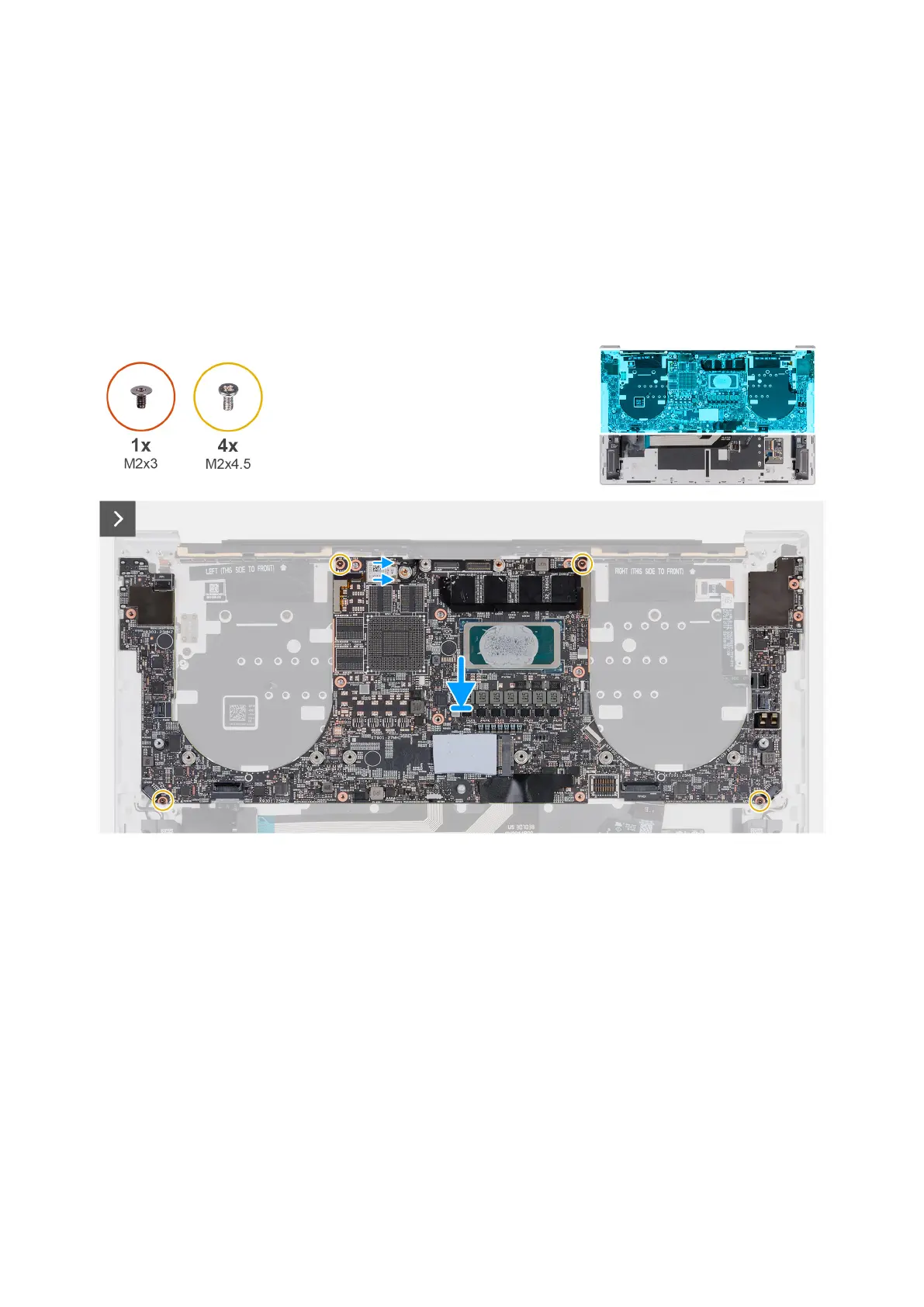
The following image(s) indicate the location of the system board and provides a visual representation of the installation
procedure.
Figure 49. Installing the system board
Removing and installing Field Replaceable Units (FRUs)
69