Prerequisites
If you are replacing a component, remove the existing component before performing the installation procedure.
About this task
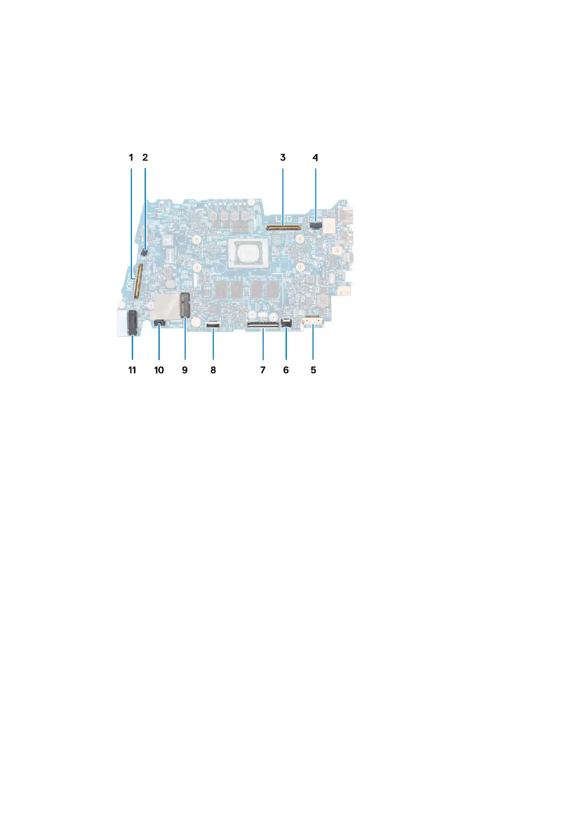
The following image indicates the connectors on your system board.
1. I/O daughter-board cable connector
2. Fan cable connector
3. Display cable connector
4. Power-adapter port cable connector
5. Battery cable connector
6. Keyboard-backlight FPC connector
7. Keyboard FPC connector
8. Touchpad FPC connector
9. Wireless card connector
10. Speaker cable connector
11. M.2 2230/2280 solid-state drive connector
The following images indicate the location of the system board and provide a visual representation of the installation procedure.
Removing and installing Field Replaceable Units (FRUs)
79
 Loading...