Getting Started Guide 11
Stack Master LED and Stack Number Display
When a switch within a stack is the master unit, the stack master LED, which
is labeled M, is solid green. If the M LED is off, the stack member is not the
master unit. The Stack No. panel displays the unit number for the stack
member. If a switch is not part of a stack, the M LED is illuminated and the
stack unit number is 1.
PowerConnect 7000 Series Back Panel
The following images show the back panel of the PowerConnect 7000 Series
switches.
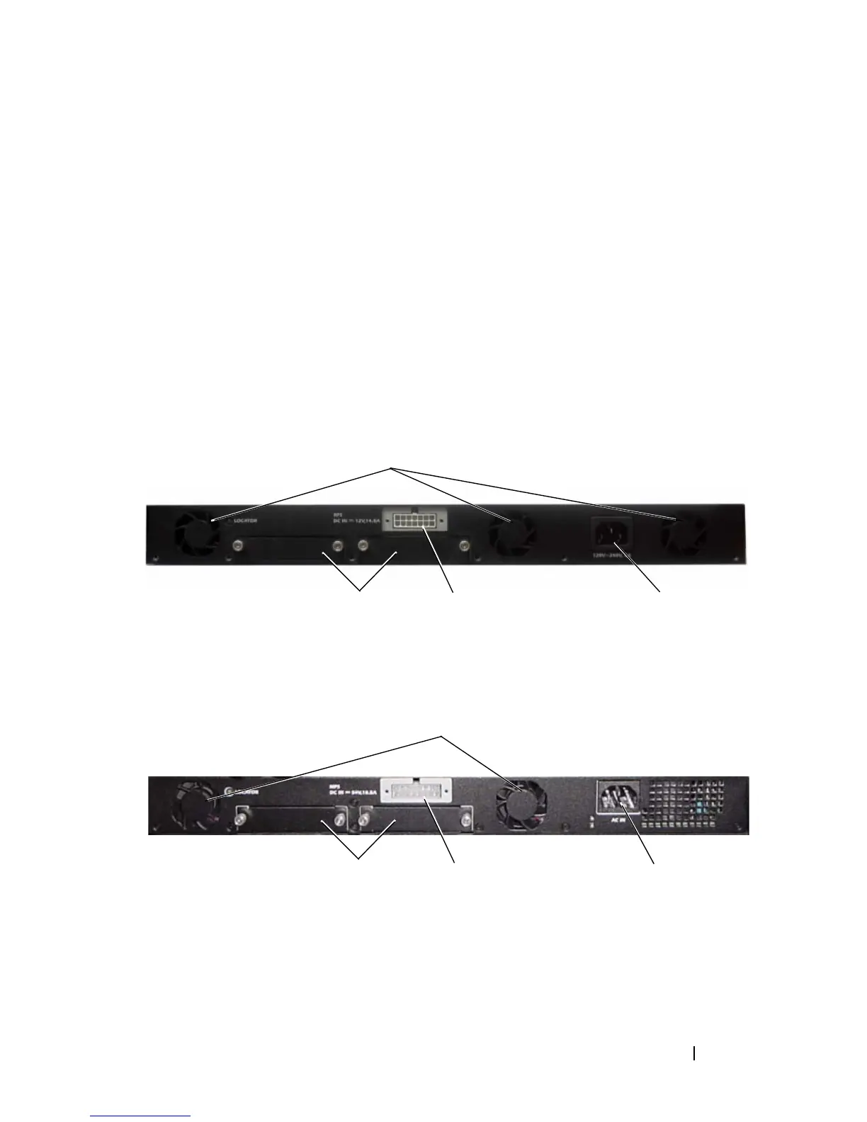
Figure 1-8. PC7024, PC7024F, and PC7048 Back Panel
Figure 1-9. PC7024P and PC7048P Back Panel
Dual 10G Slots for SFP+, 10GBASE-T,
or Stacking/10GbE Modules
AC Power
Receptacle
Redundant DC Power
Supply Receptacle
Fan Vents
AC Power
Receptacle
External DC Power
Supply Receptacle
Fan Vents
Dual 10G Slots for SFP+, 10GBASE-T,
or Stacking/10 GbE Modules
 Loading...