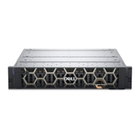
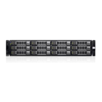
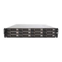
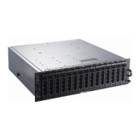
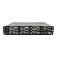
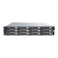
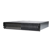
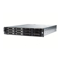
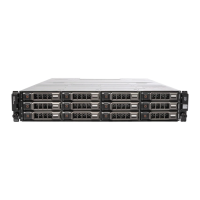
Figure 1. Enclosure front view
1. System power 2. System status
3. Enclosure ID 4. Express Service Tag
You can monitor the LEDs on the front panel area to determine system status. The following table describes the front panel
LEDs and their functions:
Table 1. Front panel LEDs
Item Indicator Description Color Status
1 System power Green
● On: System power
available (operational)
2 System fault Amber
● Blinking: System
hardware fault
3 Enclosure ID Blue
● Blinking: Identifying
enclosure
Rear panel features and indicators
The PSUs and EMMs can be accessed from the rear panel. The PSUs use alphabetic designators, and the EMMs use numeric
designators to identify the slots in an enclosure.
Figure 2. Enclosure rear panel components
1.
PSU B 2. EMM Slot 1 (side A)
3. EMM Slot 2 (side B) 4. PSU A
6 System overview

 Loading...
